Difference between revisions of "7745 Sensing Lab 2"
| Line 35: | Line 35: | ||
* Enable the input for analog in 0 by checking the appropriate checkbox. | * Enable the input for analog in 0 by checking the appropriate checkbox. | ||
| − | * Experiment further by connecting some | + | * Experiment further by connecting some additional analog sensors to pins such as ''a0'', ''a1'', ''a2'', ''a3'', ''a4'', etc. Start making an entirely new musical interaction using the sensors. Some sensing circuits are shown below. For more information, see [https://ccrma.stanford.edu/wiki/Sensors the sensors lecture]. |
| − | ** potentiometer: | + | * * potentiometer: |
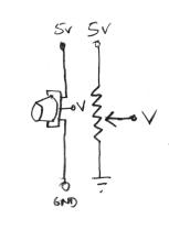
[[Image:Pot.png]] | [[Image:Pot.png]] | ||
| Line 52: | Line 52: | ||
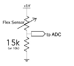
[[Image:Bend_sensor.png]] | [[Image:Bend_sensor.png]] | ||
| − | |||
| − | |||
| − | |||
| − | |||
| − | |||
| − | |||
| − | |||
| − | |||
| − | |||
| − | |||
| − | |||
| − | |||
| − | |||
| − | |||
| − | |||
Revision as of 19:09, 26 February 2014
This lab most recently revamped by Edgar Berdahl and Wendy Ju. Chris Carlson, possibly Bill Verplank, and others have likely contributed.
For this lab you need your Satellite CCRMA kit, a laptop computer with Ethernet adaptor to program it, and some headphones with a mini 1/8" (2.54mm) stereo jack.
You are also invited to bring the following optional items, but they are by no means required:
- Some of your favorite breadboardable sensors and LEDs.
- Your powered loudspeaker.
Contents
Power Up and Prepare Arduino
- Use the same procedure as described before to power up Satellite CCRMA and login as the user ccrma with the password temppwd.
- As always start by running the following command to stop the default pd patch from running
stop-default
- Then start pd by executing
pd &
Analog Circuits
Now we will work with the continuous input values provided by analog sensors - potentiometers, accelerometers, distance rangers, etc
Voltage Divider Circuit
- Open the pd patch ~/pd/labs-Music-250a-2012/lab2/
- Read the messages in the pd window and make sure that it was able to open the device on /dev/ttyUSB0 (this is the Arduino -- it's showing up as the 0th serial device).
- Enable the input for analog in 0 by checking the appropriate checkbox.
- Experiment further by connecting some additional analog sensors to pins such as a0, a1, a2, a3, a4, etc. Start making an entirely new musical interaction using the sensors. Some sensing circuits are shown below. For more information, see the sensors lecture.
- * potentiometer:
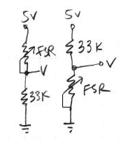
- force-sensitive resistor (FSR):
Try both circuits. Test the resistance range of your sensor. If you want 2.5 volts to be the middle, make the comparison resistor (33k in the diagram) the "average" value of the FSR's resistance. Test this with a multimeter.
- Bend Sensor
Putting it all Together
- Create a patch to make sounds based on button and sensor values from the Arduino. You can try to adapt your patches from Lab 1, or come up with a new patch. Try to make the sound good!
- Make a simple musical interaction. Think about music -
- does it have dynamics?
- can you turn the sound off?
- can it be expressive?


