Difference between revisions of "SonicAnxiety"
| (18 intermediate revisions by the same user not shown) | |||
| Line 1: | Line 1: | ||
| − | + | Sonic Anxiety is an ironic twist on performance anxiety, where the performance is the sound of anxiety while locked in a cage. Sensors track breathing to control the harmony and timbre while the BPM set by the pulse sets the pace and drum rhythms of the piece. | |
| + | |||
| + | '''Cage MIDI controller sonifys "anxiety". | ||
''' | ''' | ||
| Line 59: | Line 61: | ||
• Build the breath sensor and attach to Arduino | • Build the breath sensor and attach to Arduino | ||
| − | • Attach pulse sensor and | + | • Attach pulse sensor and accelerometers (future) to Arduino. |
• Make MAX patch which reads heart and breathing data. | • Make MAX patch which reads heart and breathing data. | ||
• Have these triggers change specific aspects of song. eg: if heart rate is increasing
after 10 seconds, shift chord quality. | • Have these triggers change specific aspects of song. eg: if heart rate is increasing
after 10 seconds, shift chord quality. | ||
• Create conditions. e.g.: if amount of oxygen is increasing and is intervals between
breaths are regular, play steady rhythm. If oxygen levels increase but breath timing irregular, then start to swing rhythm or play more syncopated beats. If oxygen levels are low and the breath timing is fast, the beats will become distorted or more randomized. | • Create conditions. e.g.: if amount of oxygen is increasing and is intervals between
breaths are regular, play steady rhythm. If oxygen levels increase but breath timing irregular, then start to swing rhythm or play more syncopated beats. If oxygen levels are low and the breath timing is fast, the beats will become distorted or more randomized. | ||
• Test out conditions to see what works | • Test out conditions to see what works | ||
| − | • Build 4 ft | + | • Build 4 ft tall cage |
| − | • Attach accelerometer to a belt or the side of cage | + | • Attach accelerometer to a belt or the side of cage (will be used in future performance) |
| − | • Make separate MAX patch for accelerometer data to be sent to Ableton to trigger | + | • Make separate MAX patch for accelerometer data to be sent to Ableton to trigger industrial samples or samples recorded when building cage |
• Attach additional pressure sensors to cage to use to make a slider for a track which can play breath and heart sounds imitating mine | • Attach additional pressure sensors to cage to use to make a slider for a track which can play breath and heart sounds imitating mine | ||
| − | |||
| − | + | ||
| + | Order of devices communicating with each other | ||
| + | |||
| + | '''Sensors > Arduino > MAX > Ableton | ||
| + | ''' | ||
| + | |||
| + | Parts Needed for Anxiety Sonification and Dramatic Effects | ||
For Breath: | For Breath: | ||
• Barometric Sensor Breakout - T5403- pressure sensor which measures absolute pressure of surround air | • Barometric Sensor Breakout - T5403- pressure sensor which measures absolute pressure of surround air | ||
• 1 ft plastic or metal tubing For Heart Rate: | • 1 ft plastic or metal tubing For Heart Rate: | ||
| − | • SEN-11574 Pulse Sensor | + | • SEN-11574 Pulse Sensor http://pulsesensor.myshopify.com |
| − | • AD8232 Single Lead Heart Rate Monitor SEN-12650? | + | • or AD8232 Single Lead Heart Rate Monitor SEN-12650? |
| − | • | + | • Wind sensor- http://moderndevice.com/product/wind-sensor/ |
| − | • | + | • RedBot Sensor - AccelerometerSEN-12589 (not used in this performance but will be in future show) https://www.sparkfun.com/products/12589 |
• Metal bars, or thick metal sheet for cage | • Metal bars, or thick metal sheet for cage | ||
• Door hinges and lock (possibly sensor for lock?) | • Door hinges and lock (possibly sensor for lock?) | ||
| − | + | • Flexiforce Pressure Sensor - RTL-11380- for direct musical controls inside the cage
(for direct controls in Ableton- also not used in this performance) | |
| − | • Flexiforce Pressure Sensor - RTL-11380- for direct musical controls inside the cage
( | + | |
| + | Sensors used in this Performance: | ||
http://moderndevice.com/product/wind-sensor/ | http://moderndevice.com/product/wind-sensor/ | ||
| − | |||
https://www.sparkfun.com/products/11574 | https://www.sparkfun.com/products/11574 | ||
| − | |||
| − | [[File:Cagedrawing.jpg]] | + | Timeline of Progress: |
| + | |||
| + | [[File:Cagedrawing.jpg]] Idea | ||
| + | |||
| + | [[File:Metal.jpg]] Metal cutting for cage bars | ||
[[File:Cagewood.jpg]] Cage partially finished (no roof) | [[File:Cagewood.jpg]] Cage partially finished (no roof) | ||
| Line 97: | Line 106: | ||
[[File:Windarduino.jpg]] Here is the wind sensor hooked up to Arduino | [[File:Windarduino.jpg]] Here is the wind sensor hooked up to Arduino | ||
| − | which has been programmed to send data to Max/MSP where it is processed in the following Max/ MSP and Max for Live patches attached. | + | which has been programmed to send data to Max/MSP where it is processed in the following Max/ MSP and Max for Live patches attached. This sensor allows for breath to be used to control the chords. |
| − | So far I have a fully functional program linking WindSensor > Arudino > Max/MSP > Max for Live > Ableton which allows my breath control the song. | + | So far I have a fully functional program linking the following devices together '''WindSensor > Arudino > Max/MSP > Max for Live > Ableton''' which allows my breath control the song. |
| Line 158: | Line 167: | ||
[[File:Control.jpg]] | [[File:Control.jpg]] | ||
| − | + | There is a strange number- throws off the "windsum" patch which should output only when the "sum" message is pressed. Luckily it is much lower then all of the averages (between 0 and 30) so the problem was fixed by filtering. | |
| − | + | ||
| + | |||
| + | The next step was to add attach the pulse sensor to the Arduino board and program it to output the BPM. | ||
| + | Initially I was able to retrieve the pulse sensor data in MAX but it was tricky combining the 2 separate Arduino codes for the wind sensor and the pulse sensor. | ||
| + | It is important to note that the Pulse sensor has an additional Interupt file which must stay in the same folder the Arduino code is saved in. | ||
| + | |||
| + | '''Here are the 2 Arduino codes for the Wind sensor and Pulse sensor combined into one Arduino: | ||
| + | ''' | ||
| + | |||
| + | |||
| + | // Demonstrates sending an multiple sensor values as serial data | ||
| + | // to Max | ||
| + | ///////////////////////////////////////////////////////////////// | ||
| + | |||
| + | // PULSE VARIABLES | ||
| + | int pulsePin = 4; // Pulse Sensor purple wire connected to analog pin 0 | ||
| + | int blinkPin = 13; // pin to blink led at each beat | ||
| + | volatile int BPM; // used to hold the pulse rate | ||
| + | volatile int Signal; // holds the incoming raw data | ||
| + | volatile int IBI = 600; // holds the time between beats, must be seeded! | ||
| + | volatile boolean Pulse = false; // true when pulse wave is high, false when it's low | ||
| + | volatile boolean QS = false; // becomes true when Arduoino finds a beat. | ||
| + | |||
| + | //WIND VARIABLES | ||
| + | #define analogPinForRV 1 // change to pins you the analog pins are using | ||
| + | #define analogPinForTMP 0 | ||
| + | const float zeroWindAdjustment = -.44; // negative numbers yield smaller wind speeds and vice versa. | ||
| + | int TMP_Therm_ADunits; //temp termistor value from wind sensor | ||
| + | float RV_Wind_ADunits; //RV output from wind sensor | ||
| + | float RV_Wind_Volts; | ||
| + | float zeroWind_ADunits; | ||
| + | float zeroWind_volts; | ||
| + | int WindSpeed_MPH; | ||
| − | + | void setup() { | |
| − | 1) | + | pinMode(blinkPin,OUTPUT); // pin that will blink to your heartbeat! |
| + | Serial.begin(57600); | ||
| + | interruptSetup(); | ||
| + | } | ||
| + | |||
| + | void loop() { | ||
| + | TMP_Therm_ADunits = analogRead(analogPinForTMP); | ||
| + | RV_Wind_ADunits = analogRead(analogPinForRV); | ||
| + | RV_Wind_Volts = (RV_Wind_ADunits * 0.0048828125); | ||
| + | zeroWind_ADunits = -0.0006*((float)TMP_Therm_ADunits * (float)TMP_Therm_ADunits) + 1.0727 * (float)TMP_Therm_ADunits + 47.172; // 13.0C 553 482.39 | ||
| + | zeroWind_volts = (zeroWind_ADunits * 0.0048828125) - zeroWindAdjustment; | ||
| + | WindSpeed_MPH = (int) pow(((RV_Wind_Volts - zeroWind_volts) /.2300) , 2.7265); | ||
| + | |||
| + | a2dStep(); | ||
| + | delay(10); | ||
| + | } | ||
| + | |||
| + | void a2dStep() { | ||
| + | int val[2]; // 2 means that it will only look | ||
| + | //at the first 2 analog pins Analog 0 and Analog 1 | ||
| + | val[0] = BPM; | ||
| + | val[1] = WindSpeed_MPH; | ||
| + | |||
| + | Serial.write(255); //send separator byte | ||
| + | |||
| + | for (int i=0; i<2; i++) { | ||
| + | Serial.write(val[i]>>3); // send 7 MSB as serial data | ||
| + | Serial.write(val[i]&7); // send 3 LSB as serial data | ||
| + | } | ||
| + | //wind sensor code - take the values that are sent to serial print in the wind sensor program and do serial.write | ||
| + | } | ||
| + | |||
| + | |||
| + | |||
| + | |||
| + | |||
| + | '''Here is the Interrupt for the pulse sensor which must stay in the same folder as the main Arduino code: | ||
| + | ''' | ||
| + | |||
| + | // Demonstrates sending an multiple sensor values as serial data | ||
| + | // to Max | ||
| + | ///////////////////////////////////////////////////////////////// | ||
| + | |||
| + | // PULSE VARIABLES | ||
| + | int pulsePin = 4; // Pulse Sensor purple wire connected to analog pin 0 | ||
| + | int blinkPin = 13; // pin to blink led at each beat | ||
| + | volatile int BPM; // used to hold the pulse rate | ||
| + | volatile int Signal; // holds the incoming raw data | ||
| + | volatile int IBI = 600; // holds the time between beats, must be seeded! | ||
| + | volatile boolean Pulse = false; // true when pulse wave is high, false when it's low | ||
| + | volatile boolean QS = false; // becomes true when Arduoino finds a beat. | ||
| + | |||
| + | //WIND VARIABLES | ||
| + | #define analogPinForRV 1 // change to pins you the analog pins are using | ||
| + | #define analogPinForTMP 0 | ||
| + | const float zeroWindAdjustment = -.44; // negative numbers yield smaller wind speeds and vice versa. | ||
| + | int TMP_Therm_ADunits; //temp termistor value from wind sensor | ||
| + | float RV_Wind_ADunits; //RV output from wind sensor | ||
| + | float RV_Wind_Volts; | ||
| + | float zeroWind_ADunits; | ||
| + | float zeroWind_volts; | ||
| + | int WindSpeed_MPH; | ||
| + | |||
| + | void setup() { | ||
| + | pinMode(blinkPin,OUTPUT); // pin that will blink to your heartbeat! | ||
| + | Serial.begin(57600); | ||
| + | interruptSetup(); | ||
| + | } | ||
| + | |||
| + | void loop() { | ||
| + | TMP_Therm_ADunits = analogRead(analogPinForTMP); | ||
| + | RV_Wind_ADunits = analogRead(analogPinForRV); | ||
| + | RV_Wind_Volts = (RV_Wind_ADunits * 0.0048828125); | ||
| + | zeroWind_ADunits = -0.0006*((float)TMP_Therm_ADunits * (float)TMP_Therm_ADunits) + 1.0727 * (float)TMP_Therm_ADunits + 47.172; // 13.0C 553 482.39 | ||
| + | zeroWind_volts = (zeroWind_ADunits * 0.0048828125) - zeroWindAdjustment; | ||
| + | WindSpeed_MPH = (int) pow(((RV_Wind_Volts - zeroWind_volts) /.2300) , 2.7265); | ||
| + | |||
| + | a2dStep(); | ||
| + | delay(10); | ||
| + | } | ||
| + | |||
| + | void a2dStep() { | ||
| + | int val[2]; // 2 means that it will only look | ||
| + | //at the first 2 analog pins Analog 0 and Analog 1 | ||
| + | val[0] = BPM; | ||
| + | val[1] = WindSpeed_MPH; | ||
| + | |||
| + | Serial.write(255); //send separator byte | ||
| + | |||
| + | for (int i=0; i<2; i++) { | ||
| + | Serial.write(val[i]>>3); // send 7 MSB as serial data | ||
| + | Serial.write(val[i]&7); // send 3 LSB as serial data | ||
| + | } | ||
| + | //wind sensor code - take the values that are sent to serial print in the wind sensor program and do serial.write | ||
| + | } | ||
| + | |||
| + | |||
| + | |||
| + | A max patch receiving multiple inputs from USB serial data had to be used. | ||
| + | |||
| + | Here is the receiver MAX patch. | ||
| + | |||
| + | [[File: Reviever.png]] This MAX patch received the data from the sensors plugged into the Arduino and then sends it out to be received and used in the MAX for Live plugins | ||
| + | |||
| + | Next, I modified and expanded upon the Max for Live trigger plug in to receive the BPM data and make it trigger the drum patters instead of the Wind sensor data | ||
| − | |||
| − | |||
| − | |||
| − | + | Project By Victoria Grace and Joel Chapman | |
Latest revision as of 14:32, 4 December 2014
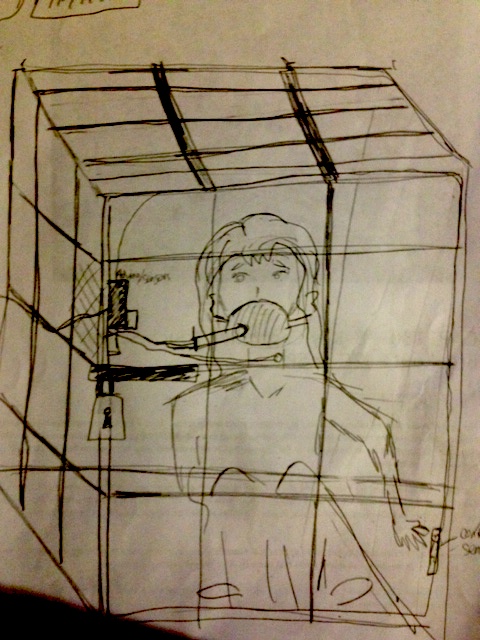
Sonic Anxiety is an ironic twist on performance anxiety, where the performance is the sound of anxiety while locked in a cage. Sensors track breathing to control the harmony and timbre while the BPM set by the pulse sets the pace and drum rhythms of the piece.
Cage MIDI controller sonifys "anxiety".
Similar or Inspiring pieces relating to breath and heart beat:
https://www.youtube.com/watch?v=GzLxrxGMMDo INSIDE-OUT is a source performance art piece by Andre Borges. The artist has a task mask on, wires attached to his chest and his hand is inside a box. We hear his breath and heart are amplified. Around 4 minutes in rattling and clanging sounds enter the room from an objects to the side of the performer. I appreciate the off-beat heart beat driving the piece forward and interacting with the other sounds heard.
http://www.instructables.com/id/Yoga-Breathalyzer/ Wind Sensor Used for Breath
http://gordophone.blogspot.com/2013/01/breath-sensing-101.html Breath Sensor with Tube
https://www.youtube.com/watch?v=n8fsMcMY2do In We Disappear (2nd half of Youtube V=video), the industrial sounds John Hopkins uses and the way he constantly manipulates the samples I admire. He keeps a relatively consistent chord profession but portrays it very differently depending on the percussive sounds laid over and additional processing effects used.
http://www.youtube.com/watch?v=rWixdA2xTSs Marina Abramovic & Ulay- Breathing In / Breathing Out (Death Itself)
http://www.youtube.com/watch?v=xEMbjnTJCHM Controlling a 4-story pipe organ with the Kinect- Ableton triggering ideas
http://www.youtube.com/watch?v=xC9XRpCOO6g Holly Herdon- Breathe
1) https://www.youtube.com/watch?v=5U_fN7NtSho 2) https://www.youtube.com/watch?v=9pn_b7OUO6I Robert Henke- using Granulating parameters
Other Inspiring Performance Art
https://www.youtube.com/watch?v=omDK2Cm2mwo&list=PLB9B4A00FC70FD6E3&index=35 RYOJI IKEDA : THE TRANSFINITE https://www.youtube.com/watch?v=3zoTKXXNQIU&list=PLB9B4A00FC70FD6E3&index=13
Technology out there already USB Breath Controller- http://www.tecontrol.se/products/usb-midi-breath-controller BC3A Microsoft Band - https://www.youtube.com/watch?v=CEvjulEJH9w
Things I need to have done for a minimal viable product: Have the breath, heart and body sensors synced with Ableton parameters with a flexible song created.
Things that you want to have done by the final deadline: All steps in the To Do list below.
Things that would be nice to have if I had unlimited time: Have accompanying visualizer responding to heart and breathing rate.
Necessary to make this idea happen:
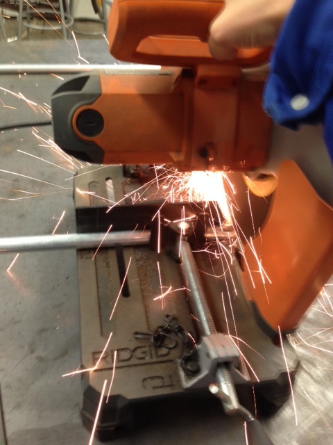
• Build the breath sensor and attach to Arduino • Attach pulse sensor and accelerometers (future) to Arduino. • Make MAX patch which reads heart and breathing data. • Have these triggers change specific aspects of song. eg: if heart rate is increasing after 10 seconds, shift chord quality. • Create conditions. e.g.: if amount of oxygen is increasing and is intervals between breaths are regular, play steady rhythm. If oxygen levels increase but breath timing irregular, then start to swing rhythm or play more syncopated beats. If oxygen levels are low and the breath timing is fast, the beats will become distorted or more randomized. • Test out conditions to see what works • Build 4 ft tall cage • Attach accelerometer to a belt or the side of cage (will be used in future performance) • Make separate MAX patch for accelerometer data to be sent to Ableton to trigger industrial samples or samples recorded when building cage • Attach additional pressure sensors to cage to use to make a slider for a track which can play breath and heart sounds imitating mine
Order of devices communicating with each other
Sensors > Arduino > MAX > Ableton
Parts Needed for Anxiety Sonification and Dramatic Effects
For Breath: • Barometric Sensor Breakout - T5403- pressure sensor which measures absolute pressure of surround air • 1 ft plastic or metal tubing For Heart Rate: • SEN-11574 Pulse Sensor http://pulsesensor.myshopify.com • or AD8232 Single Lead Heart Rate Monitor SEN-12650? • Wind sensor- http://moderndevice.com/product/wind-sensor/ • RedBot Sensor - AccelerometerSEN-12589 (not used in this performance but will be in future show) https://www.sparkfun.com/products/12589 • Metal bars, or thick metal sheet for cage • Door hinges and lock (possibly sensor for lock?) • Flexiforce Pressure Sensor - RTL-11380- for direct musical controls inside the cage (for direct controls in Ableton- also not used in this performance)
Sensors used in this Performance: http://moderndevice.com/product/wind-sensor/ https://www.sparkfun.com/products/11574
Timeline of Progress:
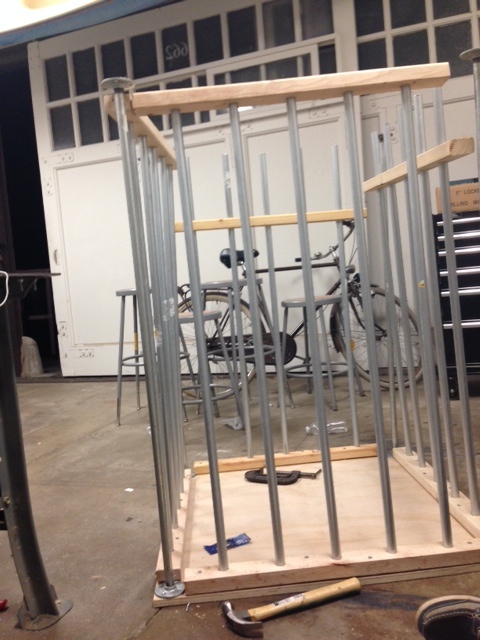 Cage partially finished (no roof)
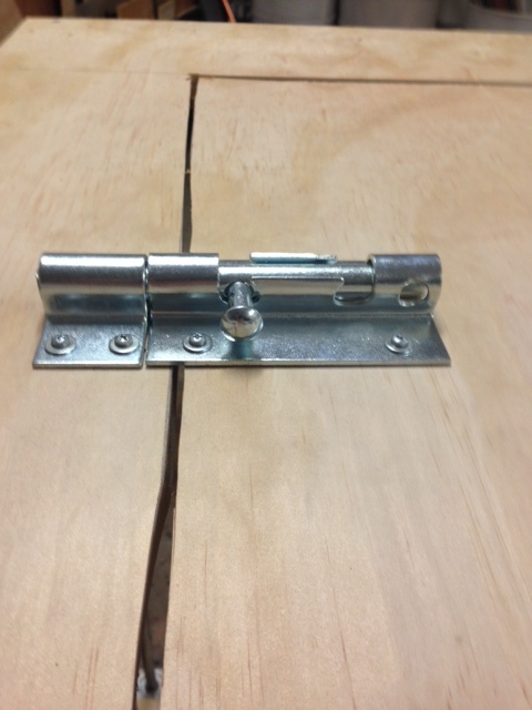 Roof: only opening in cage is through the hatch on top
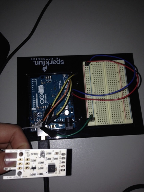 Here is the wind sensor hooked up to Arduino
which has been programmed to send data to Max/MSP where it is processed in the following Max/ MSP and Max for Live patches attached. This sensor allows for breath to be used to control the chords.
So far I have a fully functional program linking the following devices together WindSensor > Arudino > Max/MSP > Max for Live > Ableton which allows my breath control the song.
Here is the Hardware set up I used.
  Hardware Setup:
 Wind Sensor Signals    Arduino
GND                           GND
+V                              5V
RV                              A1
TMP                            A0

This Arduino code I used to calibrate the Wind Sensor that I based on the information and code can be found on Paul Badger website [[1]]
There initially was an issue with the serial port which for some reason needed to be 57600. Also, the sensor was outputting a float value which could not be sent over serial and needed to be converted to an int.
 Serial.begin(57600);
  int i;
i = (int) WindSpeed_MPH;


   //  Serial.write(255);	//send separator byte
Initially I used the serial print function to see the incoming data from the sensor which later was changed to write to output the data to Max.
Serial.write(i);
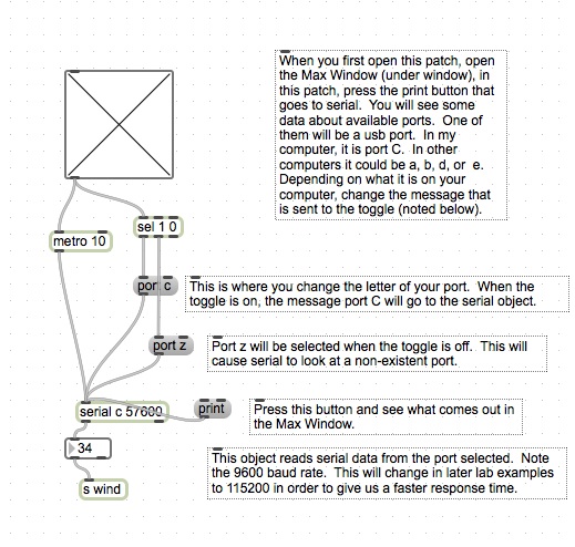 The Max patch I used to receive data was based on a simplified version of Sasha Leitman's Max patch from Lab which received data from a single sensor.
From there I send out wind (the "s Wind" object) which is returned as inputs into my effects control patches included below:'
I made a sample Ableton session with selection of different chords and drum patters which I each put on different tracks.
Track 1 has different loops of samples of sounds I recorded while building the cage.
Track 2 are various short drum patters which also loop.
Track 3 are single chords.
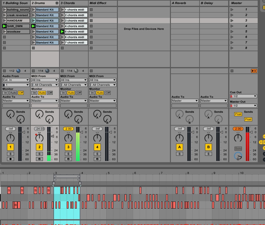 Currently I have written two different types Max for Live patches. Ones that constantly change the value of an effect based on the sensor output, and another which switches tracks based on a condition set.
First I made a simple bit crusher Audio effect I made in Max for Live and hooked it up to the Wind sensor data. When no wind is present the sensor reads around 35 and when you blow will full force into the wind sensor, the number decreases to 0. I scaled this data in the bit crusher to set the range of the BitRate between 1 and 24. The result is when you blow into the sensor more distortion is added to the track in Ableton.
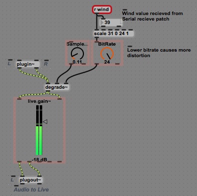 My simple "Bit Crusher" Max for Live patch in Max for Live.
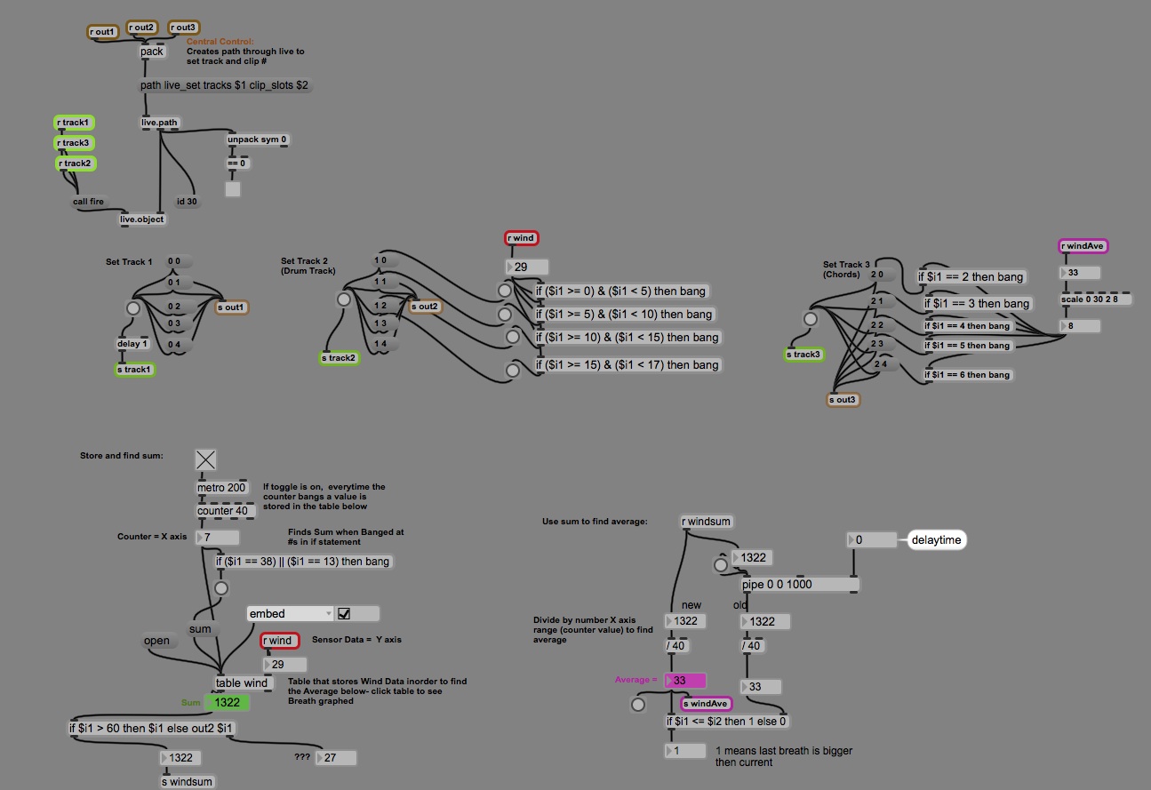
I made a Max patch which communicated with Ableton as a whole instead of directly controlling the sound in an individual track. This is different from a default MIDI or Audio Max for Live effect.
This is the first part of the patch below where it is labeled "Central Control" in brown.
Below the Central Control are the groups of slot triggers for tracks 1, 2 $ 3. If statements filter the direct Wind data to trigger different samples for Track 2 which has different banks of MIDI drum patterns.
Since the value the sensor is outputting, "Wind", is changing about every 20 ms, I found it inconvenient to use this method in Track 2 to accomplish my goal for smoothly changing the chords. I decided the program should wait as long a few breaths would take and find the average "Wind" which can be compared to the previous time interval to determine if amount of breath is increasing or decreasing.
The patch which stores all the recent Wind values and takes the average can be found on the lower part of the Max patch.
There is a strange number- throws off the "windsum" patch which should output only when the "sum" message is pressed. Luckily it is much lower then all of the averages (between 0 and 30) so the problem was fixed by filtering.
The next step was to add attach the pulse sensor to the Arduino board and program it to output the BPM.
Initially I was able to retrieve the pulse sensor data in MAX but it was tricky combining the 2 separate Arduino codes for the wind sensor and the pulse sensor.
It is important to note that the Pulse sensor has an additional Interupt file which must stay in the same folder the Arduino code is saved in.
Here are the 2 Arduino codes for the Wind sensor and Pulse sensor combined into one Arduino:
// Demonstrates sending an multiple sensor values as serial data
// to Max
/////////////////////////////////////////////////////////////////
// PULSE VARIABLES
int pulsePin = 4;                 // Pulse Sensor purple wire connected to analog pin 0
int blinkPin = 13;                // pin to blink led at each beat
volatile int BPM;                   // used to hold the pulse rate
volatile int Signal;                // holds the incoming raw data
volatile int IBI = 600;             // holds the time between beats, must be seeded!
volatile boolean Pulse = false;     // true when pulse wave is high, false when it's low
volatile boolean QS = false;        // becomes true when Arduoino finds a beat.
//WIND VARIABLES
#define analogPinForRV    1   // change to pins you the analog pins are using
#define analogPinForTMP   0
const float zeroWindAdjustment =  -.44; // negative numbers yield smaller wind speeds and vice versa.
int TMP_Therm_ADunits;  //temp termistor value from wind sensor
float RV_Wind_ADunits;    //RV output from wind sensor
float RV_Wind_Volts;
float zeroWind_ADunits;
float zeroWind_volts;
int WindSpeed_MPH;

void setup() {
 pinMode(blinkPin,OUTPUT);         // pin that will blink to your heartbeat!
 Serial.begin(57600);
 interruptSetup();
}
void loop() {
 TMP_Therm_ADunits = analogRead(analogPinForTMP);
   RV_Wind_ADunits = analogRead(analogPinForRV);
   RV_Wind_Volts = (RV_Wind_ADunits *  0.0048828125);
 zeroWind_ADunits = -0.0006*((float)TMP_Therm_ADunits * (float)TMP_Therm_ADunits) + 1.0727 * (float)TMP_Therm_ADunits + 47.172;  //  13.0C  553  482.39
   zeroWind_volts = (zeroWind_ADunits * 0.0048828125) - zeroWindAdjustment;
   WindSpeed_MPH = (int) pow(((RV_Wind_Volts - zeroWind_volts) /.2300) , 2.7265);

 a2dStep();
 delay(10);
}
void a2dStep() {
 int val[2];           // 2 means that it will only look
                       //at the first 2 analog pins Analog 0 and Analog 1
 val[0] = BPM;
 val[1] = WindSpeed_MPH;

 Serial.write(255);	//send separator byte
 for (int i=0; i<2; i++) {
   Serial.write(val[i]>>3);    // send 7 MSB as serial data
   Serial.write(val[i]&7);	 // send 3 LSB as serial data
 }
//wind sensor code - take the values that are sent to serial print in the wind sensor program and do serial.write
}
Here is the Interrupt for the pulse sensor which must stay in the same folder as the main Arduino code:
// Demonstrates sending an multiple sensor values as serial data
// to Max
/////////////////////////////////////////////////////////////////
// PULSE VARIABLES
int pulsePin = 4;                 // Pulse Sensor purple wire connected to analog pin 0
int blinkPin = 13;                // pin to blink led at each beat
volatile int BPM;                   // used to hold the pulse rate
volatile int Signal;                // holds the incoming raw data
volatile int IBI = 600;             // holds the time between beats, must be seeded!
volatile boolean Pulse = false;     // true when pulse wave is high, false when it's low
volatile boolean QS = false;        // becomes true when Arduoino finds a beat.
//WIND VARIABLES
#define analogPinForRV    1   // change to pins you the analog pins are using
#define analogPinForTMP   0
const float zeroWindAdjustment =  -.44; // negative numbers yield smaller wind speeds and vice versa.
int TMP_Therm_ADunits;  //temp termistor value from wind sensor
float RV_Wind_ADunits;    //RV output from wind sensor
float RV_Wind_Volts;
float zeroWind_ADunits;
float zeroWind_volts;
int WindSpeed_MPH;

void setup() {
 pinMode(blinkPin,OUTPUT);         // pin that will blink to your heartbeat!
 Serial.begin(57600);
 interruptSetup();
}
void loop() {
 TMP_Therm_ADunits = analogRead(analogPinForTMP);
   RV_Wind_ADunits = analogRead(analogPinForRV);
   RV_Wind_Volts = (RV_Wind_ADunits *  0.0048828125);
 zeroWind_ADunits = -0.0006*((float)TMP_Therm_ADunits * (float)TMP_Therm_ADunits) + 1.0727 * (float)TMP_Therm_ADunits + 47.172;  //  13.0C  553    482.39
   zeroWind_volts = (zeroWind_ADunits * 0.0048828125) - zeroWindAdjustment;
   WindSpeed_MPH = (int) pow(((RV_Wind_Volts - zeroWind_volts) /.2300) , 2.7265);

 a2dStep();
 delay(10);
}
void a2dStep() {
 int val[2];           // 2 means that it will only look
                       //at the first 2 analog pins Analog 0 and Analog 1
 val[0] = BPM;
 val[1] = WindSpeed_MPH;

 Serial.write(255);	//send separator byte
 for (int i=0; i<2; i++) {
   Serial.write(val[i]>>3);    // send 7 MSB as serial data
   Serial.write(val[i]&7);	 // send 3 LSB as serial data
 }
//wind sensor code - take the values that are sent to serial print in the wind sensor program and do serial.write
}
A max patch receiving multiple inputs from USB serial data had to be used.
Here is the receiver MAX patch.
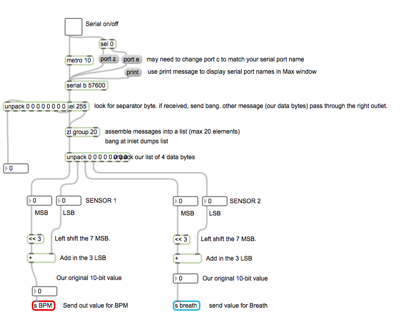 This MAX patch received the data from the sensors plugged into the Arduino and then sends it out to be received and used in the MAX for Live plugins
Next, I modified and expanded upon the Max for Live trigger plug in to receive the BPM data and make it trigger the drum patters instead of the Wind sensor data
Project By Victoria Grace and Joel Chapman
