Difference between revisions of "220c Spring 2018 ~bjosie"
(→Technical Adjustments) |
|||
| (One intermediate revision by the same user not shown) | |||
| Line 105: | Line 105: | ||
-Surface should not be as far off of the ground | -Surface should not be as far off of the ground | ||
| + | |||
-Pedal should be narrower | -Pedal should be narrower | ||
| + | |||
-A bit longer might be more useful | -A bit longer might be more useful | ||
| + | |||
-The pads should be more space efficient: less tall and a wider pad area | -The pads should be more space efficient: less tall and a wider pad area | ||
| + | |||
-Whole housing should be made out of a durable, manufacturable material (this will be no small feat. Research into this will probably represent the most important phase of moving forward with the physical design) | -Whole housing should be made out of a durable, manufacturable material (this will be no small feat. Research into this will probably represent the most important phase of moving forward with the physical design) | ||
| Line 113: | Line 117: | ||
-Making this bluetooth-enabled will provide for more flexibility. I have microcontrollers with bluetooth capability, but they cannot output MIDI, so converting that will be its own task | -Making this bluetooth-enabled will provide for more flexibility. I have microcontrollers with bluetooth capability, but they cannot output MIDI, so converting that will be its own task | ||
| + | |||
-Adjusting the circuit so that a 9v power supply will work with it - currently, it can only take in a 5v power supply (which are far less common) | -Adjusting the circuit so that a 9v power supply will work with it - currently, it can only take in a 5v power supply (which are far less common) | ||
| + | |||
-Making this a "three-dimensional" expressive MIDI controller.... | -Making this a "three-dimensional" expressive MIDI controller.... | ||
Latest revision as of 23:12, 4 June 2018
Contents
Phase I - Analog
Although I consider myself a guitar pedal enthusiast, I had never explored the creation of an analog pedal myself. I have seen countless product demonstrations, and as my understanding of electronics has expanded over my time at Stanford, I have been wondering how I might gain a greater understanding of the circuitry involved in the sound sculpture in pedals, or at least a greater insight of their design.
After coming across a couple wah pedals in the Max Lab, I made the logical step of tearing them open to inspect the insides.
With one note reading "Scratchy sound when pot is moved," these pedals were in the junk bin for a reason. They were not in superb shape for practical use, but I was lucky they were extremely intact, and I could explore the insides. I found circuit diagrams for a simple wah as well as the specific wah in question and compared the diagram with the actual pedal.
After several trials of removing/swapping resistors, capacitors and potentiometers, I began to realize the circuit was less interesting to me than was the design of the pedal itself. The mechanics of the tilted surface, the rolling pot, and the way the designers filled the housing piqued my interest. This became even more evident when I busted open my Boss SD-1. Boss, a company whose name has become synonymous with indestructible, sure knows how this process works.
Each piece of the pedal is placed extremely intentionally, using rugged materials and leaving nothing to luck. The insides were all screwed into place, and it was rather straightforward to be able to deconstruct. Inside, wires were even zip-tied to be directed into place.
In this exploration, I realized two things: Nine weeks would not provide me with enough time to meaningfully understand the workings of an analog circuit; I am more intrigued by the physical design anyway, which makes me ready to move onto....
Phase II - Digital
In 250a, I used electronics for the first time to create what I deemed a digital pedalboard called ToeCandy. While the finished design itself is extremely basic and not tremendously practical, the idea of a digital pedalboard has stuck with me, and I have not seen one in the time since I took 250a.
The idea would be to create a system of FSRs to be able to send MIDI control data to any DAW to use as analog signal to affect any parameter of the user's choosing. In the design I am hoping to create, each pedal would have one FSR/control surface, but the beauty would be it's ability to be multiplexed, with a handful of pedals working together, able to affect a number of parameters at any time. The design would be a small housing, hopefully not much bigger than a standard guitar pedal, so that it can attach to any standard pedalboard.
As the design develops, it wirelessly transmit data to your device, as well as wirelessly connect to other pedals to transmit each pedal's data through one BlueTooth channel.
Early Sketches
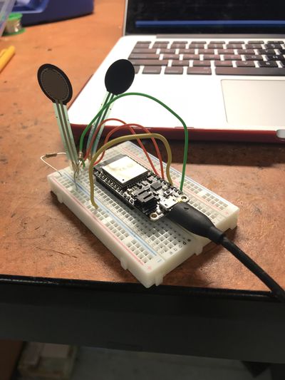
The above picture shows a microcontroller with two force sensors, to build the simple circuit as the basis for the pedal. The planned design is to have a tilted platform with to ~squishy~ pads resting atop the force sensors as the primary user interface. The requirements of the circuit are rather small, and moving forward with a first prototype should not be too difficult.
First Prototype
Physical Model
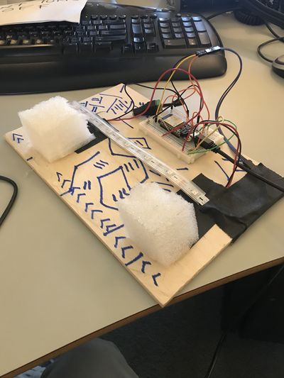
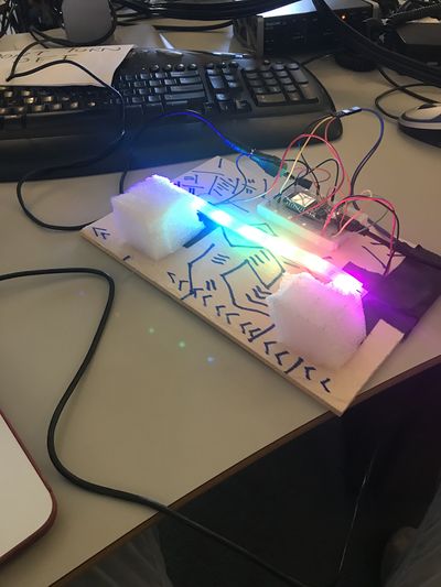
The above images show the first prototype of the pedal. The FSR's sit on the board, wired to the microcontroller, giving analog voltages which the microcontroller computes to output a meaningful MIDI control value. The foam pads help to absorb some of the pressure put by the user's foot control. Without these pads, the FSR's would be much too sensitive to utilize any meaningful control output. The LED strip was put in place to indicate to the user their output without having to monitor their computer at the same time. Adafruit's NeoPixel was used for this function, which can allow the whole strip to be controlled on an LED-by-LED basis, using only one digital out pin on the controller.
Code
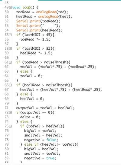
The above image demonstrates the primary loop of the microcontroller's computations. It takes voltage readings from both the heel and toe, then proportionately calculates the output value. Additionally, output values on the extreme are more rapidly changed, to allow for quick sweeps when the user desires such.
Second Prototype
In this first version, I was able to get a sense of what it might look like, while knowing that a much more thoroughly-developed model would be needed in the near future. To allow for another rapid prototyping, its housing would be made entirely from wood, and the circuit would remain relatively the same. Then comes the problem of the interface pads. Something more flexible and durable was needed, so silicone becomes the ideal material. I would have to first create the mold into which I could pour and cast the silicone.
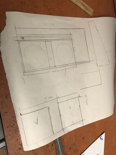
Woodcutting
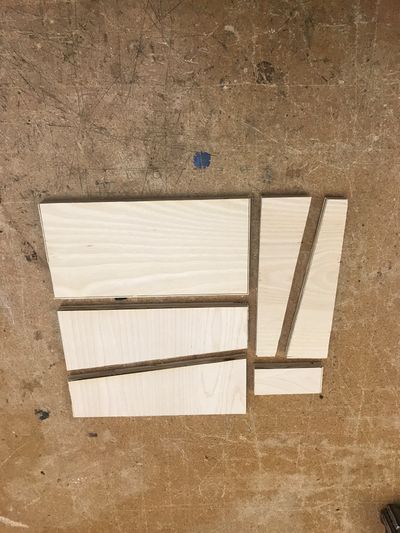
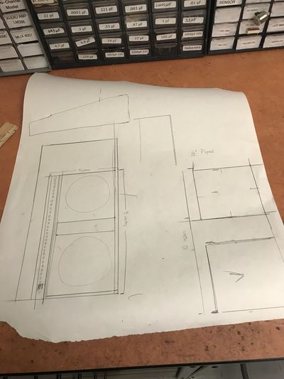
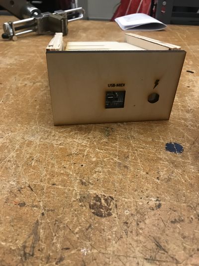
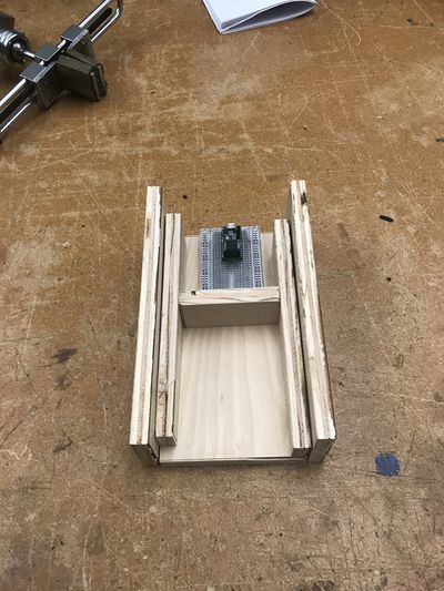
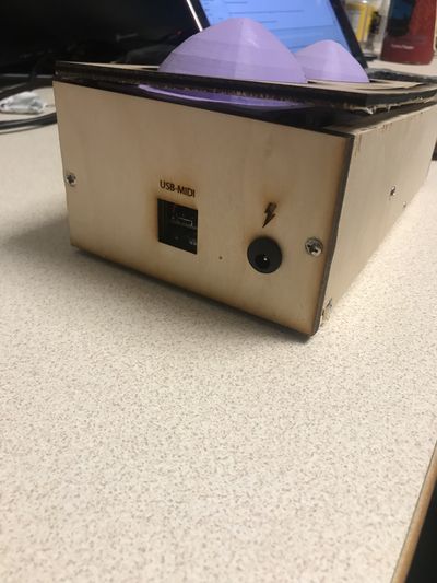
The woodcutting was relatively simple. After deciding on the general sizes, I was able to laser-cut the measurements into the wood (for extra precision) before taking the pieces to the table saw. Additional pieces of thinner wood were laser cut for faces which 1/2-inch wood would be too thick. This laser-cut wood also allowed more flexibility to allow power in and access to the USB port.
Silicone Casting
Upon starting this phase of the project, I had never worked with silicone. I had to research the different methods and available materials to see what I might be able to utilize. Ultimately, it seemed like I would make a 3d model of the mold (another process I had never done before) and pour the silicone with the softest durometer-rated silicone on eagerplastics.com
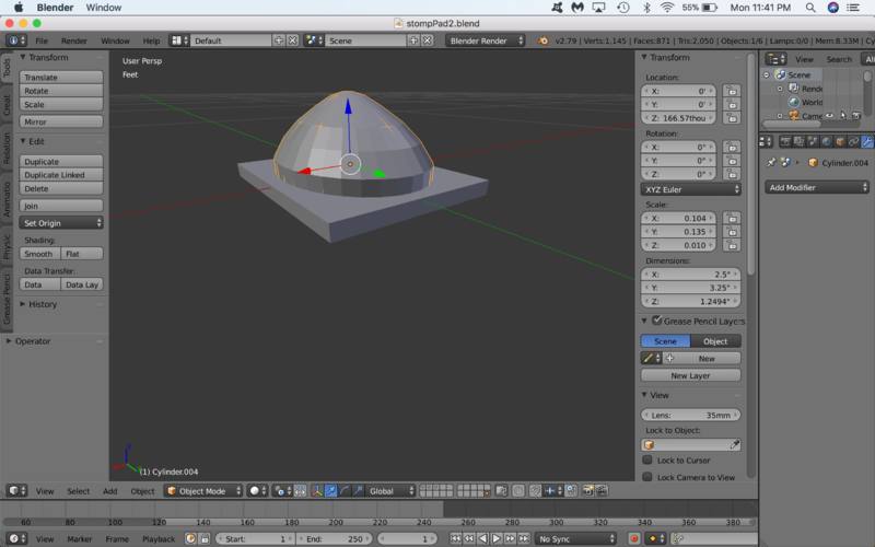
I downloaded blender and looked at tutorials until I had learned enough to make the shape of the pad.
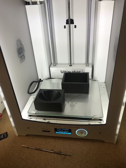
Then, through a simple process, created the mold for this shape. The mold was uploaded into ultimaker, where the 3d printer was able to print the shape (it only took 22 hours!)
This is the silicone used in the process:
After a thorough mixing, the silicone could be poured into the mold, and left to harden. The whole process takes about 4 hours.
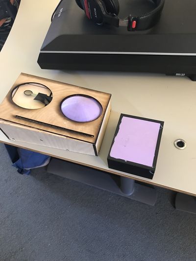
Finished Product
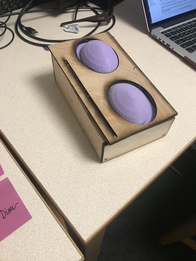
Future of ToeCandy
I have had a blast working on this project. It has been a great way to survey a ton of building processes as they combine together for a single goal. I have had this idea, in some form, for about a year and a half now, and it has been extremely rewarding to bring that to a reality this quarter. I plan to continue working on this, with tangible adjustments in mind:
Form Adjustments
-Surface should not be as far off of the ground
-Pedal should be narrower
-A bit longer might be more useful
-The pads should be more space efficient: less tall and a wider pad area
-Whole housing should be made out of a durable, manufacturable material (this will be no small feat. Research into this will probably represent the most important phase of moving forward with the physical design)
Technical Adjustments
-Making this bluetooth-enabled will provide for more flexibility. I have microcontrollers with bluetooth capability, but they cannot output MIDI, so converting that will be its own task
-Adjusting the circuit so that a 9v power supply will work with it - currently, it can only take in a 5v power supply (which are far less common)
-Making this a "three-dimensional" expressive MIDI controller....
3D MIDI Expression
With only two extra FSRs in the circuit, this pedal can be made tremendously more powerful. If each pad has the ability to control its own value in the X-direction, in addition to the mapping between the two pads. This function is what separates the FSR-squishy-pad design from the typical expression pedal which can only tilt in one direction. This design allows the user to limitless mapping possibilities, and will be the focus of the next phase of this design process.
