Difference between revisions of "Introduction to Electronics"
| (48 intermediate revisions by 3 users not shown) | |||
| Line 1: | Line 1: | ||
| + | Created by: Carr Wilkerson, Edgar Berdahl, Wendy Ju, Michael Gurevich, and others | ||
| + | |||
| + | ==Electrical Circuit== | ||
| + | An interconnection of electrical elements that contains a closed loop is an '''[http://en.wikipedia.org/wiki/Electrical_network electrical circuit]'''. The closed loop allows electrons to flow through the electrical elements. We now explain how to analyze simple electrical circuits in terms of voltage, current, and resistance. | ||
| + | |||
==Current, Voltage, Resistance== | ==Current, Voltage, Resistance== | ||
| − | '''Current''' describes the quantity of electrons passing through a point in a circuit at a given instant in time. | + | '''[http://en.wikipedia.org/wiki/Electric_current Current]''' describes the quantity of electrons passing through a point in a circuit at a given instant in time. |
| − | Current is measured in '''Amperes''' ('''Amps''', '''A'''). | + | Current is measured in '''[http://en.wikipedia.org/wiki/Ampere Amperes]''' ('''Amps''', '''A'''). |
| − | '''Voltage''' describes the potential difference in electrical charge between two points in an electrical circuit. '''Voltage''' (also known as ''' | + | '''[http://en.wikipedia.org/wiki/Voltage Voltage]''' describes the potential difference in electrical charge between two points in an electrical circuit. '''Voltage''' (also known as '''electric potential''') is measured in '''[http://en.wikipedia.org/wiki/Volt Volts]''' ('''V'''). |
| − | '''Resistance''' (a special case of '''Impedance''') describes the capacity of a circuit element to resist or impede the flow of electrons in the circuit. '''Resistance''' in | + | '''[http://en.wikipedia.org/wiki/Electrical_resistance Resistance]''' (a special case of '''[http://en.wikipedia.org/wiki/Electrical_impedance Impedance]''') describes the capacity of a circuit element to resist or impede the flow of electrons in the circuit. '''Resistance''' in measured in '''[http://en.wikipedia.org/wiki/Ohm_%28unit%29 Ohms]'''. |
| − | A common analogy may be used to relate these three quantities to water flow in pipes in place of electrons in wires | + | A common analogy may be used to relate these three quantities to water flow in pipes in place of electrons in wires. Imagine you have two water tanks connected from the bottoms by a pipe (such as the drain of a double sink). If one tank is full of water and the other one nearly empty we know intuitively that the water in the full tank will flow through the pipe into the nearly empty tank. |
| − | + | <center> | |
| + | [[Image:slide1.jpg]] | ||
| + | </center> | ||
| − | |||
| − | + | Current '''I<sub>0</sub>''' is analogous to the quantity of water flowing through a pipe at a given moment in time. | |
==Ohm's Law== | ==Ohm's Law== | ||
| Line 27: | Line 33: | ||
The voltage in the circuit is given (10V from the battery) and the resistance is also given as the 100 ohm resistor is the only resistive element in the circuit. So we can compute the current in the circuit as: I = V/R = 10V / 100 Ohms = 0.1 Amps or 100 milli-Amps. | The voltage in the circuit is given (10V from the battery) and the resistance is also given as the 100 ohm resistor is the only resistive element in the circuit. So we can compute the current in the circuit as: I = V/R = 10V / 100 Ohms = 0.1 Amps or 100 milli-Amps. | ||
| + | |||
==Button LED Example== | ==Button LED Example== | ||
| − | The following circuit diagram | + | The following circuit diagram shows the most basic [http://en.wikipedia.org/wiki/LED LED (Light Emitting Diode)] circuit: |
<center> | <center> | ||
| Line 36: | Line 43: | ||
</center> | </center> | ||
| − | Diodes are from the family of semiconductors. Unlike a resistors, diodes always have a fixed voltage drop in a circuit. A diode passes current in only one direction, a very useful property for protecting circuits from incorrect current flow. The arrow in the diode symbol points in the direction that current flows, so normally you would place a diode in your circuit with the arrow pointing to a ground. Therefore once we know the current passing through the resistor in this circuit we also know the current passing through the LED. The brightness of an LED is proportional to the amount of current passing through it. How would you make the LED shine brighter? less brightly? | + | For a red LED, Vled is often about 1.7V. Diodes are from the family of semiconductors. Unlike a resistors, diodes always have a fixed voltage drop in a circuit. A diode passes current in only one direction, a very useful property for protecting circuits from incorrect current flow. The arrow in the diode symbol points in the direction that current flows, so normally you would place a diode in your circuit with the arrow pointing to a ground. Kirchoff's Current Law implies that the current flowing throught the resistor is the same as the current flowing through the LED. Therefore, once we know the current passing through the resistor in this circuit, we also know the current passing through the LED. The brightness of an LED is proportional to the amount of current passing through it. How would you make the LED shine brighter? less brightly? |
Now consider the following circuit which adds a button: | Now consider the following circuit which adds a button: | ||
| Line 45: | Line 52: | ||
The button simply interrupts or re-connects the flow of current through the circuit lighting or extinguishing the LED in the process. | The button simply interrupts or re-connects the flow of current through the circuit lighting or extinguishing the LED in the process. | ||
| + | |||
| + | ==Calculating Power (P = VI)== | ||
| + | |||
| + | Calculating the power dissipated by a circuit element is simple. Often much of this power is converted into heat, so by thinking about the power dissipated by circuit elements, you can make sure that they don't burn up or catch on fire! | ||
| + | |||
| + | Power (in Watts) = Voltage (in Volts) x Current (in Amps) P = V I Combining with Ohm's law we get two other useful forms: P = V*V / R and P = I*I*R Power is a measurement of the amount of work that can be done with the circuit, such as turning a motor or lighting a light bulb. Consider a 100Watt light bulb in your home. We know the voltage applied to the bulb is normally 110V or 220V so we can calculate the current consumed as follows: I = P/V = 100W / 110V = 0.91 Amps or I = P/V = 100W / 220V = 0.45 Amps So you can see why using a 60W light buld is more economical. Your electric company normally charges you for your usage in Killo-Watt Hours (kWh). One kWh is the amount of energy necessary to do 1000 Watts of energy for one hour - in other words to keep 10 100W light bulbs shining for one hour. | ||
| + | |||
| + | ==Kirchhoff's Voltage Law== | ||
| + | |||
| + | In order to be able to analyze more complicated circuits, we need to introduce two more circuit concepts. The first is known as [http://en.wikipedia.org/wiki/Kirchhoff's_circuit_laws Kirchhoff's Voltage Law]. It is usually stated as, "The sum of the voltages around any closed circuit must be zero." An important consequence is that ''the voltage across each branch in a circuit is the same.'' This explains why the voltages across the battery and across the resistor in the above circuit are the same. | ||
| + | |||
| + | Here are important consequences of Kirchhoff's Voltage Law. See if you can derive them: | ||
| + | # '''Voltages sum in series.''' | ||
| + | # '''Electrical components placed in series all share the same current.''' | ||
| + | |||
| + | ==Kirchhoff's Current Law== | ||
| + | |||
| + | Electrical components are connected together by ''nodes'' in the total [http://en.wikipedia.org/wiki/Electrical_network network] of elements. [http://en.wikipedia.org/wiki/Kirchhoff's_circuit_laws Kirchhoff's Current Law] states that the sum of the currents entering a node must equal the sum of the currents leaving a node. This law is a consequence of the conservation of charge (electrons) in electrical networks. | ||
| + | |||
| + | |||
| + | Here are some important consequences of Kirchhoff's Current Law. See if you can derive them.: | ||
| + | # '''Currents sum in parallel.''' | ||
| + | # '''The ends of electrical components connected by a wire all share the same voltage.''' | ||
| + | |||
| + | ==Series Circuits== | ||
| + | |||
| + | Consider this slightly more complicated circuit: | ||
<center> | <center> | ||
| − | [[ | + | [[Image:series_1.png]] |
</center> | </center> | ||
| + | When two resistors are connected in series, their combined resistance is equivalent to the sum of their individual resistances. | ||
| + | |||
| + | <center> | ||
| + | [[Image:series_2.png]] | ||
| + | </center> | ||
| + | |||
| + | We can use Ohm's law to calculate the voltage drop around each of the individual resistors after calculating the voltage drop accross the total resistance. | ||
| + | |||
| + | We can further rationalize the series circuit by going back to our analogy: | ||
| + | <center> | ||
| + | [[Image:Slide2.jpg]] | ||
| + | </center> | ||
| + | |||
| + | ==Parallel Circuits== | ||
| + | |||
| + | <center> | ||
| + | [[Image:parallel_1.png]] | ||
| + | </center> | ||
| + | |||
| + | When two resistors are placed in parallel in a circuit, their combined resistance is equal to the product of the individual resistances divided by their sum. (Smaller total voltage for parallel in contrast to larger for series). | ||
| + | |||
| + | <center> | ||
| + | [[Image:parallel_2.png]] | ||
| + | </center> | ||
| + | |||
| + | One again we use ohm's law to calculate the voltage across the resistors (same for both) and the current through each resistor. | ||
| + | |||
| + | |||
| + | Here we use the water analogy again: | ||
| + | <center> | ||
| + | [[Image:Slide3.jpg]] | ||
| + | </center> | ||
| + | |||
| + | ==Voltage Divider== | ||
| + | |||
| + | <center> | ||
| + | [[Image:Slide4.jpg]] | ||
| + | </center> | ||
| + | |||
| + | |||
| + | ==Pull-up and Pull-down resistors== | ||
| + | |||
| + | Often we would like to set a "default voltage" for a circuit. This is done using pull-up and pull down resistors. | ||
| + | |||
| + | Here is an example of a pull-down resistor in a circuit. When the switch is closed, Vout=Vin, but if the switch is open, Vout=Ground. | ||
| + | |||
| + | <center> | ||
| + | [[Image:Pull-down_circuit.gif]] | ||
| + | </center> | ||
| + | Here is an example of a pull-up resistor in a circuit. When the switch is not on any lead, Vout is high. | ||
| + | <center> | ||
| + | [[Image:Pull-up_circuit.gif]] | ||
| + | </center> | ||
| + | |||
| + | In general, the R values for pull-up and pull-down resistors should be very large, much larger than those in the rest of the circuit, so that the effect of the pull-up or pull-down resistor on the Vout voltage is small if there is any else "down the line" of the circuit. | ||
| + | |||
| + | <center> | ||
| + | [[PID 2007]] | ||
| + | </center> | ||
[[Category:PID]][[Category:PID_2007]] | [[Category:PID]][[Category:PID_2007]] | ||
Latest revision as of 10:13, 25 July 2022
Created by: Carr Wilkerson, Edgar Berdahl, Wendy Ju, Michael Gurevich, and others
Contents
Electrical Circuit
An interconnection of electrical elements that contains a closed loop is an electrical circuit. The closed loop allows electrons to flow through the electrical elements. We now explain how to analyze simple electrical circuits in terms of voltage, current, and resistance.
Current, Voltage, Resistance
Current describes the quantity of electrons passing through a point in a circuit at a given instant in time. Current is measured in Amperes (Amps, A).
Voltage describes the potential difference in electrical charge between two points in an electrical circuit. Voltage (also known as electric potential) is measured in Volts (V).
Resistance (a special case of Impedance) describes the capacity of a circuit element to resist or impede the flow of electrons in the circuit. Resistance in measured in Ohms.
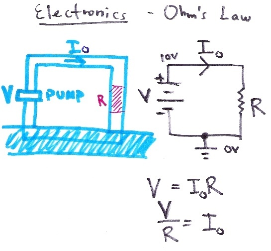
A common analogy may be used to relate these three quantities to water flow in pipes in place of electrons in wires. Imagine you have two water tanks connected from the bottoms by a pipe (such as the drain of a double sink). If one tank is full of water and the other one nearly empty we know intuitively that the water in the full tank will flow through the pipe into the nearly empty tank.
Current I0 is analogous to the quantity of water flowing through a pipe at a given moment in time.
Ohm's Law
V = IR Ohm's Law states that Voltage = Current x Resistance or V = IR. The equation can be rearranged to find any one of the three quantities given the other two.
Consider the following circuit:
The voltage in the circuit is given (10V from the battery) and the resistance is also given as the 100 ohm resistor is the only resistive element in the circuit. So we can compute the current in the circuit as: I = V/R = 10V / 100 Ohms = 0.1 Amps or 100 milli-Amps.
Button LED Example
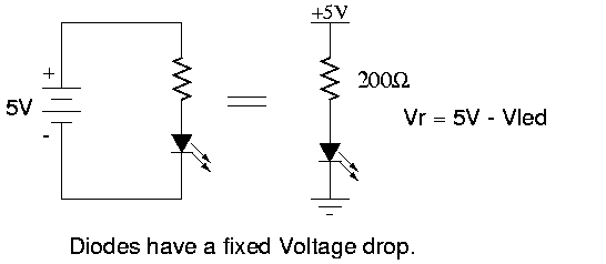
The following circuit diagram shows the most basic LED (Light Emitting Diode) circuit:
For a red LED, Vled is often about 1.7V. Diodes are from the family of semiconductors. Unlike a resistors, diodes always have a fixed voltage drop in a circuit. A diode passes current in only one direction, a very useful property for protecting circuits from incorrect current flow. The arrow in the diode symbol points in the direction that current flows, so normally you would place a diode in your circuit with the arrow pointing to a ground. Kirchoff's Current Law implies that the current flowing throught the resistor is the same as the current flowing through the LED. Therefore, once we know the current passing through the resistor in this circuit, we also know the current passing through the LED. The brightness of an LED is proportional to the amount of current passing through it. How would you make the LED shine brighter? less brightly?
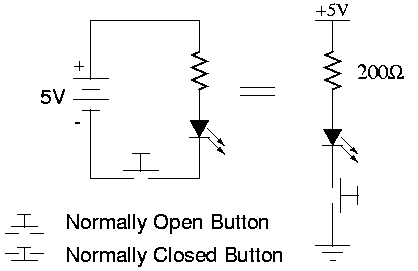
Now consider the following circuit which adds a button:
The button simply interrupts or re-connects the flow of current through the circuit lighting or extinguishing the LED in the process.
Calculating Power (P = VI)
Calculating the power dissipated by a circuit element is simple. Often much of this power is converted into heat, so by thinking about the power dissipated by circuit elements, you can make sure that they don't burn up or catch on fire!
Power (in Watts) = Voltage (in Volts) x Current (in Amps) P = V I Combining with Ohm's law we get two other useful forms: P = V*V / R and P = I*I*R Power is a measurement of the amount of work that can be done with the circuit, such as turning a motor or lighting a light bulb. Consider a 100Watt light bulb in your home. We know the voltage applied to the bulb is normally 110V or 220V so we can calculate the current consumed as follows: I = P/V = 100W / 110V = 0.91 Amps or I = P/V = 100W / 220V = 0.45 Amps So you can see why using a 60W light buld is more economical. Your electric company normally charges you for your usage in Killo-Watt Hours (kWh). One kWh is the amount of energy necessary to do 1000 Watts of energy for one hour - in other words to keep 10 100W light bulbs shining for one hour.
Kirchhoff's Voltage Law
In order to be able to analyze more complicated circuits, we need to introduce two more circuit concepts. The first is known as Kirchhoff's Voltage Law. It is usually stated as, "The sum of the voltages around any closed circuit must be zero." An important consequence is that the voltage across each branch in a circuit is the same. This explains why the voltages across the battery and across the resistor in the above circuit are the same.
Here are important consequences of Kirchhoff's Voltage Law. See if you can derive them:
- Voltages sum in series.
- Electrical components placed in series all share the same current.
Kirchhoff's Current Law
Electrical components are connected together by nodes in the total network of elements. Kirchhoff's Current Law states that the sum of the currents entering a node must equal the sum of the currents leaving a node. This law is a consequence of the conservation of charge (electrons) in electrical networks.
Here are some important consequences of Kirchhoff's Current Law. See if you can derive them.:
- Currents sum in parallel.
- The ends of electrical components connected by a wire all share the same voltage.
Series Circuits
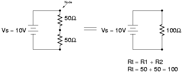
Consider this slightly more complicated circuit:
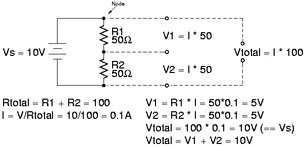
When two resistors are connected in series, their combined resistance is equivalent to the sum of their individual resistances.
We can use Ohm's law to calculate the voltage drop around each of the individual resistors after calculating the voltage drop accross the total resistance.
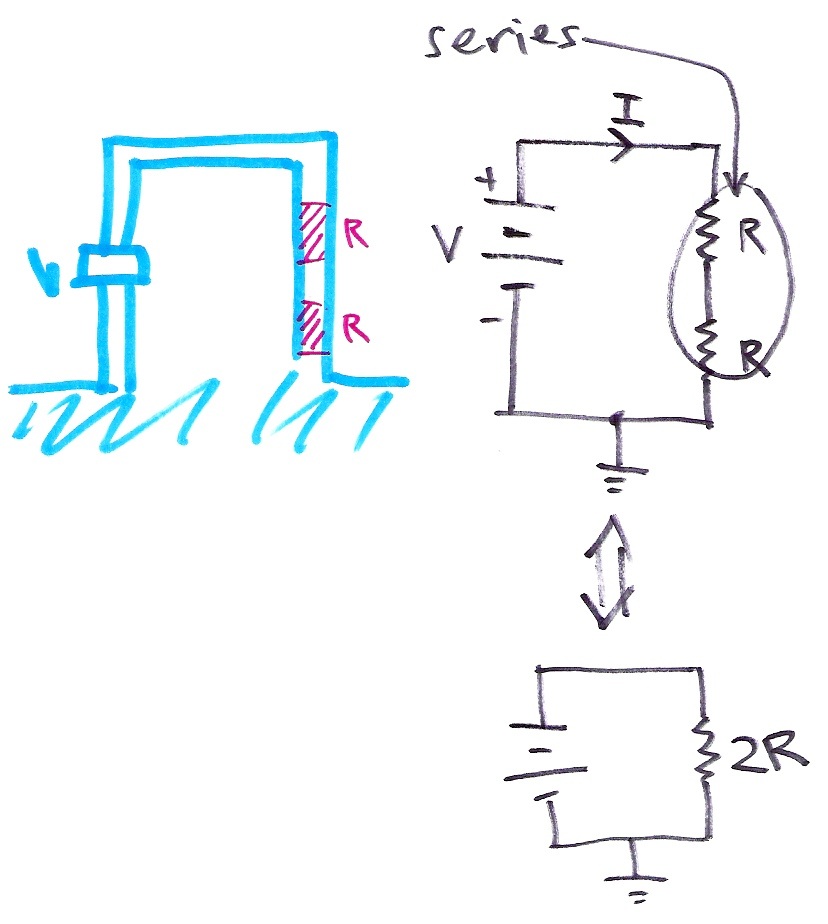
We can further rationalize the series circuit by going back to our analogy:
Parallel Circuits
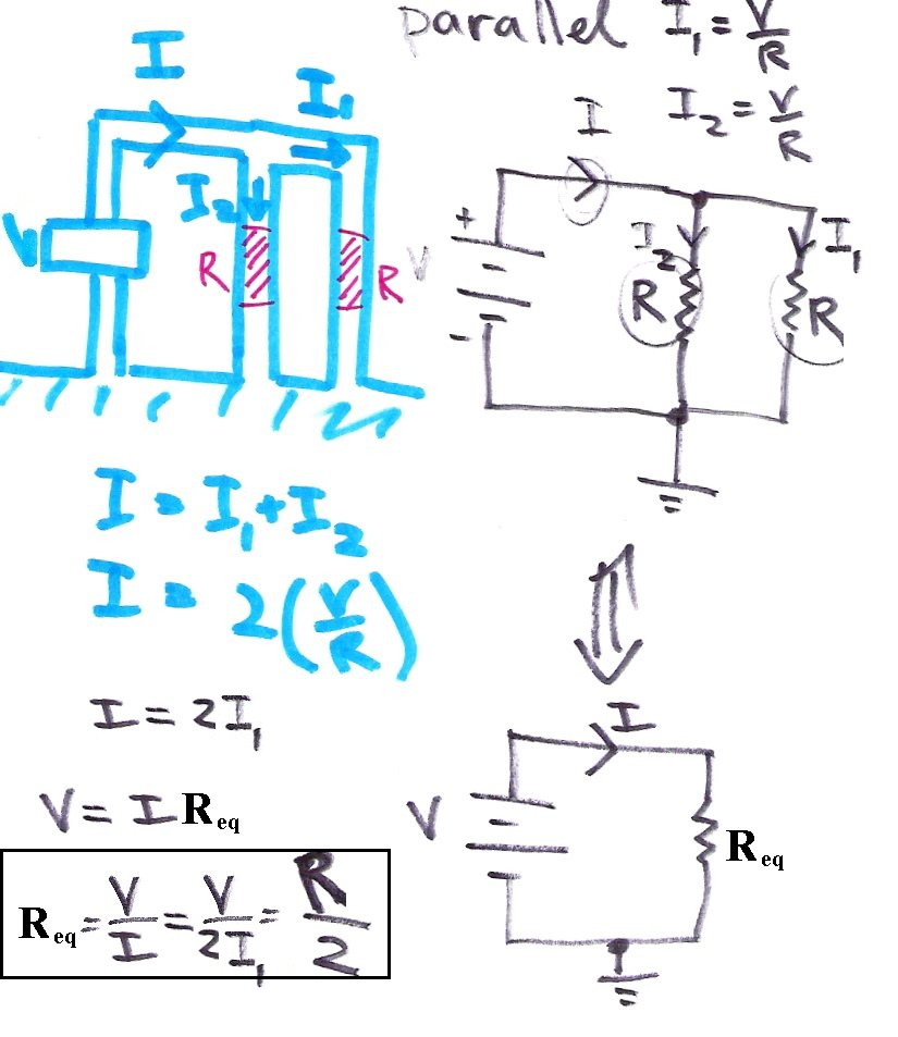
When two resistors are placed in parallel in a circuit, their combined resistance is equal to the product of the individual resistances divided by their sum. (Smaller total voltage for parallel in contrast to larger for series).
One again we use ohm's law to calculate the voltage across the resistors (same for both) and the current through each resistor.
Here we use the water analogy again:
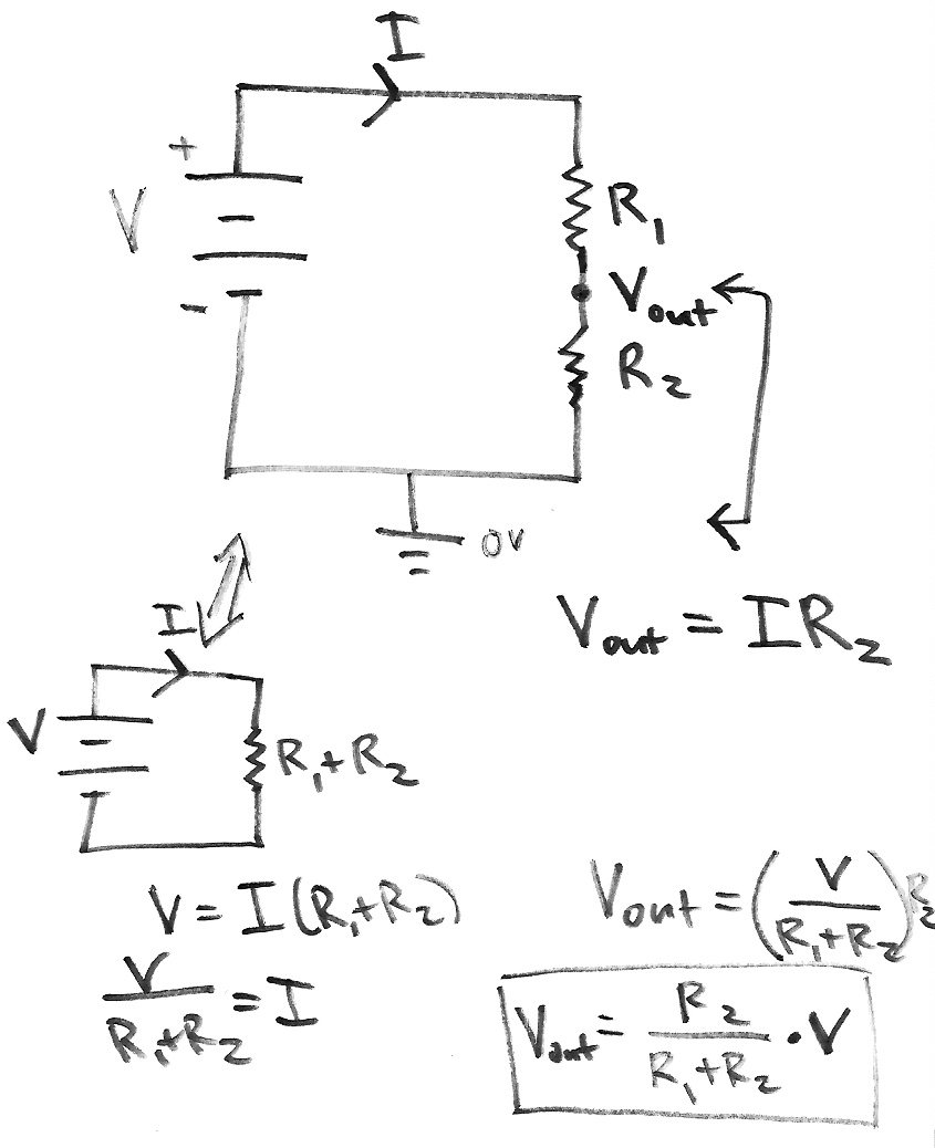
Voltage Divider
Pull-up and Pull-down resistors
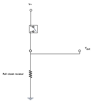
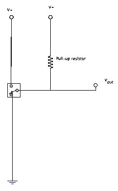
Often we would like to set a "default voltage" for a circuit. This is done using pull-up and pull down resistors.
Here is an example of a pull-down resistor in a circuit. When the switch is closed, Vout=Vin, but if the switch is open, Vout=Ground.
Here is an example of a pull-up resistor in a circuit. When the switch is not on any lead, Vout is high.
In general, the R values for pull-up and pull-down resistors should be very large, much larger than those in the rest of the circuit, so that the effect of the pull-up or pull-down resistor on the Vout voltage is small if there is any else "down the line" of the circuit.
