PID2008 Lab Two: Difference between revisions
Appearance
No edit summary |
No edit summary |
||
| (5 intermediate revisions by 2 users not shown) | |||
| Line 1: | Line 1: | ||
<font size=5>Lab | <font size=5>Lab 2: Circuits, Sensors, OSC</font><br> | ||
Assigned | Assigned Tuesday July 8 | ||
| Line 8: | Line 8: | ||
== Load meter.c onto the AVRmini == | == Load meter.c onto the AVRmini == | ||
=== Create a | === Create a lab2 Directory === | ||
~> cd | ~> cd pid2008/ | ||
~/ | ~/pid2008> mkdir lab2 | ||
*Copy avrlib-demos/meter there. | *Copy avrlib-demos/meter there. | ||
~/ | ~/pid2008> cd lab2 | ||
~/ | ~/pid2008/lab2> cp -r ../avrlib-demos/meter . | ||
=== Load the "meter" onto the AVR === | === Load the "meter" onto the AVR === | ||
~/ | ~/pid2008/lab2> cd meter | ||
~ | ~pid2008/lab2/meter> make load | ||
* This will turn your AVRmini into a rudimentary multimeter with two inputs. Use a jumper from the point at which you want to measure the voltage to A0 or A1 on the AVRmini. The voltages will be shown on the LCD. | * This will turn your AVRmini into a rudimentary multimeter with two inputs. Use a jumper from the point at which you want to measure the voltage to A0 or A1 on the AVRmini. The voltages will be shown on the LCD. | ||
| Line 90: | Line 90: | ||
Using osctest.c (in the avrlib-demos): | Using osctest.c (in the avrlib-demos): | ||
~> cd ~/ | ~> cd ~/pid2008/lab2 | ||
~/ | ~/pid2008/lab2> cp -r ../avrlib-demos/osctest . | ||
~/ | ~/pid2008/lab2> cd osctest | ||
~/ | ~/pid2008/lab2/osctest> make load | ||
and osctest.pd: | and osctest.pd: | ||
~/ | ~/pid2008/lab2/osctest> pd osctest.pd & | ||
send data from your protoboard circuits (analog input on A0 and A1), and to PD. | send data from your protoboard circuits (analog input on A0 and A1), and to PD. | ||
Latest revision as of 20:54, 6 July 2008
Lab 2: Circuits, Sensors, OSC
Assigned Tuesday July 8
For this lab you need your AVR , Power Supply, Jumpers, Resistors, Sensors and one LED from the MaxLab.
Sensors: 2-buttons, 2-potentiometers, FSR, photo-resistor, IR Emitter-Detectors.
Load meter.c onto the AVRmini
Create a lab2 Directory
                ~> cd pid2008/
        ~/pid2008> mkdir lab2
- Copy avrlib-demos/meter there.
        ~/pid2008> cd lab2
   ~/pid2008/lab2> cp -r ../avrlib-demos/meter .
Load the "meter" onto the AVR
        ~/pid2008/lab2> cd meter
   ~pid2008/lab2/meter> make load
- This will turn your AVRmini into a rudimentary multimeter with two inputs. Use a jumper from the point at which you want to measure the voltage to A0 or A1 on the AVRmini. The voltages will be shown on the LCD.
- Note that the signals are numbered starting at zero (A0 - A7) while the pins on the header that carry those signals are numbered starting at one (1 - 8). The 8-bit analog to digital conversion gives 0..255.
- Here is the pin-out for PORTA, PORTB, PORTC, PORTD (only 1.2 and 9.10 are labelled on the board):
    2  4  6  8  10
    1  3  5  7  9
- The same pin configuration is shown bellow with the signal names.
    A1  A3  A5  A7  5V
    A0  A2  A4  A6  GND
Build Sensor Circuits
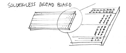
- Build the circuit that is detailed in the folowing figures. Use components and jumpers to construct your circuits on the solderless bread-board.
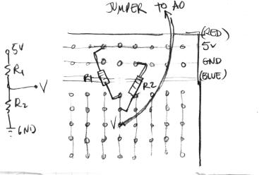
- Here's how to wire a simple 2-resistor circuit on the solderless bread-board (for example R1 = 10K, R2 = 10K):
What will A0 read?
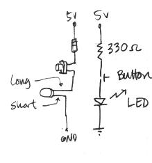
Build the Button and LED Circuit
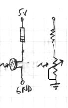
- On the left is the circuit, on the right, the diagram.
- Try replacing the one button with two buttons in series or in parallel.
Hook-up Sensors to A0 or A1 and Watch the Voltage Change
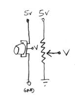
- potentiometer:
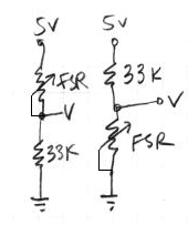
- force-sensitive resistor (FSR):
Try both circuits. Test the resistance range of your sensor. If you want 2.5 volts to be the middle, make the comparison resistor (33k in the diagram) the "average" value of the FSR's resistance. Test this with a multimeter.
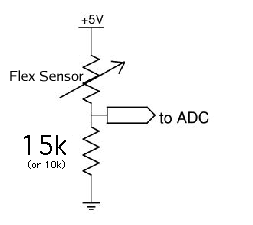
- Bend Sensor
- photo-resistor:
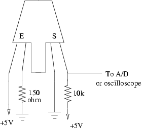
- Reflective Optical Sensor:
The Musical AVRmini
- The program running on the AVR will beep at frequencies controlled by the voltages on A0 and A1 when you press buttons on S6 and S7 on the display. Wire up four buttons to each of the B4-7 pins (this are the pins B4, B5, B6 and B7 in PORT B) according to one of these two circuits. (The one on the left is recommended -- it is at 5v unless the button is pressed.) Check that you can read in the AVR display the buttons on port B4-7.
Read Sensor Values to PD
Using osctest.c (in the avrlib-demos):
                         ~> cd ~/pid2008/lab2
            ~/pid2008/lab2> cp -r ../avrlib-demos/osctest .
            ~/pid2008/lab2> cd osctest
    ~/pid2008/lab2/osctest> make load
and osctest.pd:
~/pid2008/lab2/osctest> pd osctest.pd &
send data from your protoboard circuits (analog input on A0 and A1), and to PD.
- Note: we use the Pd [serialIO] object to read OSC data from the serial port. When you open a patch containing a [serialIO] object, you must send it a [start] message in order to begin polling the USB port. If you want to reprogram your AVR, you should send [serialIO] a [close] message to release the port for the AVR downloader to use, then you can do a make load. When you want to resume using [serialIO], you should send it a message [open /dev/ttyUSB0] to reopen the port, followed by [start] to resume polling.
- Let A0 "float" while A1 is tied to a potentiometer by removing the wire from its socket. What happens to A0's value when A1 is changed? Try the same experiment with the PORTB[4-7] buttons. Why does this happen? How can we prevent it?
Putting it all Together
- Create a Pd patch to make sounds based on button and sensor values from the AVR. You can try to adapt your patch from Lab 1, or come up with a new patch. You can also use as a starting point the patch osctestsoundout.pd, located in the same folder.
- Try to make a simple musical interaction. Think about music -
- does it have dynamics?
- can you turn the sound off?
- can it be expressive?
- You may need to make a copy of osctest and modify it to send the appropriate control signals.
