Difference between revisions of "Sensors"
(→Force Sensing Resistors) |
(→Force Sensing Resistors) |
||
| Line 84: | Line 84: | ||
<center> | <center> | ||
| − | [[Image:FSR. | + | [[Image:FSR.png]] |
</center> | </center> | ||
Revision as of 13:32, 28 June 2007
This is a brief overview with some practical circuits of some of the sensors we use in Physical Interaction Design for Music at CCRMA. For a great music sensor reference, see SensorWiki.org.
Contents
PushButtons and Switches
Switches are the simplest group of discrete sensors. They act as a valve, opening or closing the flow of electrons through a branch of your circuit.
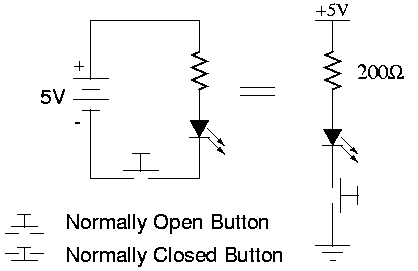
Switches can be interfaced directly to a microcontroller's digital input requiring only a pull-up resistor.
Switch nomenclature:
- SPDT - Single Pole, Double Throw. Has three contacts, signal of interest would normally go in the middle and is connected to one of the two other contact depending on the switch position.
- DPDT - Double Pole, Double Throw. Has the same structure as the SPST but with a second set of contact so two signal can be switched together.
- Normally Open - The contacts are connected only while the button is actuated. aka. Momentary Contact
- Normally Closed - The contacts are connected except while the button is actuated.
- Toggle - Toggles between closed and open with each actuation
There are many other types of switches, mechanical, electrical (transistors, photo-transistors ...), and combinations of the two (solenoids ...).
Potentiometers
Potentiometers (Pots) are the simplest group of continuous sensors. A potentiometer is a special resistor with a third movable contact, called a wiper. A pot has a fixed resistance from one end to the other as does a normal resistor, but the resistance between the wiper and the ends changes as the wiper is moved (one gets smaller as the other gets larger - the always add up to the fixed resistance between the fixed ends). For rotary pots, the wiper moves as the shaft turns. For linear or slide pots, the wiper moves with the slider.
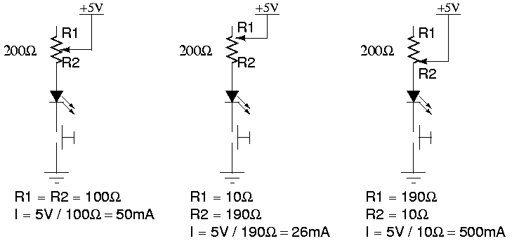
A potentiometer is normally interfaced to a microcontroller by digitizing the voltage found across it using an ADC( Analog to digital converter ). An alternate method for determining the value of a potentiometer is to place it in an RC circuit and measure the decay time
Potentiometer nomenclature:
- trim pot - A small potentiometer often used for calibrating a circuit. It usually requires a screw driver to turn and is intended to be set and left alone.
- turns - Some pots cover their range of resistance with only one turn while other can take ten or more turns. The multi-turn pots afford greater precision, but normally cost more and obviously take longer to turn!
- taper - The "taper" of a pot refers to the curve formed by plotting the rotation (for a rotary pot) or displacement (for a slide pot) on the X-axis and resistance between the pin 1 and the wiper (R1 above) on the Y-axis. A "linear" taper would have a straight line, such that at 180 degrees rotation, the resistance is half of the total resistance. In "Logarithmic" (or "Log" or "Audio") taper pots the resistance changes logarithmically with rotation. These pots are commonly used in analog audio mixers because humans perceve logarithmic changes in loudness roughly linearly.
Reflective Optical Sensor
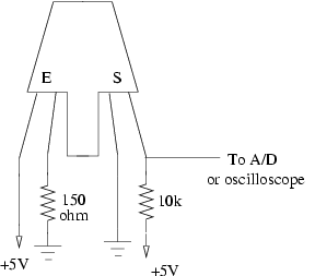
The reflective optical sensor consists of an infrared LED and a phototransistor that passes an amount of current proportional to the reflected light received. We use two kinds at CCRMA, the Fairchild QRB1114 has the letter "E" (Emitter) to label the LED, and the label "S" (Sensor) for the phototransistor. The Optek OPB704 uses the symbols for an LED and a transistor to label the two sides. One leg of the sensor is connected to +5V, which supplies current, and the voltage drop across the 10k resistor that we measure is proportional to the amount of current.
There is a continuous voltage response for objects over a short range of proximity to the sensor. The response is not linear. Linearity can be approximated by the log of the log of the signal.
Quadrature Encoders

The above diagram demonstrates two signals in a quadrature relationship. The most common sensor we use that has this kind of signal is a rotary encoder or shaft encoder. Rotary encoders are normally optical (expensive) or mechanical (cheap). A mechanical encoder works simply by connecting the Phase A and Phase B pins (pins 1 and 3 in the diagram below) to a common pin (pin 2), according to a quadrature pattern. Wired up as in the diagram, pins 1 and 3 will go to ground when when connected to pin 2, and will be high when they are not. Mechanical contacts inside the encoder create the quadrature signals as above. An optical encoder may function similarly using LEDs and phototransistors as in the IR sensor above, with alternating dark/light patterns applied in quadrature.
Note that Phase A leads Phase B by 90 degrees when looking from left to right. Looking from right to left the opposite is true. We use quadrature encoders with the external interrupt on a microcontroller. By connecting the Phase A pin to an interrupt, we can generate an interrupt SIGNAL (function call) every time it transitions from low to high. In the interrupt, we can check the state of the Phase B pin. If B is low when A goes high, then we have moved to the right. If B is high when A goes high, then we know we have moved to the left. Shaft encoders are rated with a number of counts or ticks per complete rotation. Note that if we attach both Phase B and Phase A to external interrupts, we can double the resolution.
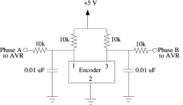
This filter circuit helps to stabilize the output of the shaft encoder and reduces noise by introducing pull-up resistors and low pass filters with cut-off frequency of ~ 1.6kHz on each of the two output pins.
Features
Shaft encoders normally turn infinitely. If we know the number of counts, we can keep track of the absolute position of the shaft. By measuring the time between ticks (or between some number of ticks), we can calculate velocity. Also, using an IR reflective object sensor and some custom printed paper, for example, you can build your own quadrature encoder. There is NO A/D conversion involved in using a shaft encoder! Shaft encoders are commonly used in automation and robotics conjunction with motors to achieve accurate positioning. They are also ubiquitous on volume knobs in stereo equipment.
Bend Sensor
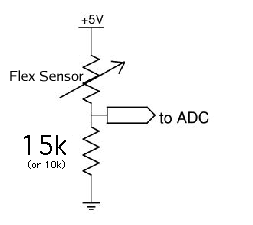
The bend or flex sensor (Jameco #150551) has a nominal resistance of 10k ohms. It goes to about 70k ohms when maximally bent. A voltage divider with a resistor R2 of 47k ohms gives a range of 4.12 Volts to 2 Volts.
Force Sensing Resistors
- Notes below are from the lecture notes of the former CCRMA Music 252 Course

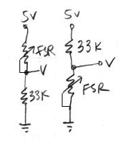
As their name implies, force sensing resistors use the electrical property of resistance to measure the force (or pressure) applied to a sensor. A force sensing resistor is made up of two parts. The first is a resistive material applied to a film. The second is a set of digitating contacts applied to another film. Figure 5 shows this configuration. The resistive material serves to make an electrical path between the two sets of conductors on the other film. When a force is applied to this sensor, a better connection is made between the contacts, hence the conductivity is increased. Over a wide range of forces, it turns out that the conductivity (the inverse of resistance) is approximately a linear function of force . The figure below shows the resistance of the sensor as a function of force. It is important to note the three regions of operation of the sensor. The first is the abrupt transition which occurs somewhere in the vicinity of 10 grams of force. In this region the resistance changes very rapidly. This behavior is useful when one is designing switches using FSRs. Above this region, the force is approximately proportional to 1/R until a saturation region is reached. When forces reach this magnitude, additional forces do not decrease the resistance substantially.
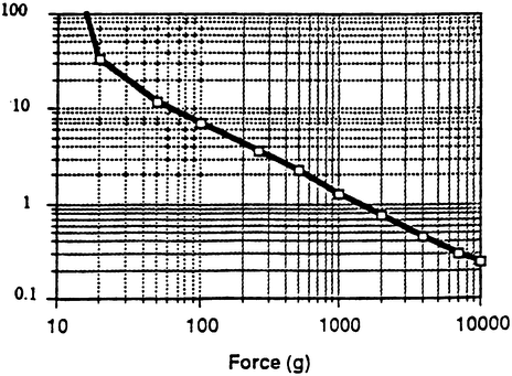
The figure below shows a plot of conductance versus force for a typical FSR sensor. Notice that the x-axis is now a linear axis, and that above the break-point, conductance is approximately linear with force. It is important to make note of the fact that FSRs are not appropriate for accurate measurements of force due to the fact that parts might exhibit as much as 15% to 25% variation between each other.

Accelerometers
- Notes below are from the lecture notes of the former CCRMA Music 252 Course
- We now use the Triple Axis Accelerometer Breakout - LIS3LV02DQ from Sparkfun

The basic physical principle behind many accelerometers is that of a simple mass spring system. Springs (within their linear region) are governed by a physical principle known as Hooke's law. Hooke's law states that a spring will exhibit a restoring force which is proportional to the amount it has been stretched or compressed. Specifically, F=kx, where k is the constant of proportionality between displacement (x) and force (F). The other important physical principle is that of Newton's second law of motion which states that a force operating on a mass which is accelerated will exhibit a force with a magnitude F=ma. The above figure shows a mass connected to a spring. If this system undergoes an acceleration, then by Newton's law, there will be a resultant force equal to ma. This force causes the mass to either compress or expand the spring under the constraint that F=ma=kx. Hence an acceleration a will cause the mass to be displaced by x=ma/k or alternatively, if we observe a displacement of x, we know that the mass has undergone an acceleration of a=kx/m. In this way we have turned the problem of measuring acceleration into one of measuring the displacement of a mass connected to a spring. Note that this system only responds to accelerations along the length of the spring. This is said to be a single axis accelerometer. In order to measure multiple axes of acceleration, this system needs to be duplicated along each of the required axes.
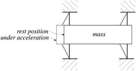
The Analog Devices ADXL50 is a micro-machined stand-alone accelerometer which consists of a mass spring system as well as a system to measure displacement and the appropriate signal conditioning circuitry (which is the topic of the next section). The mass spring system used in this device is depicted in Figure 9. The mass is a bar of silicon, and the spring system is implemented by the 4 tethers which attach to each corner of the mass. It responds to accelerations that occur in line with the length of the mass. When an acceleration occurs, the mass moves with respect to the anchored ends of the tethers. Roughly speaking, the amount of acceleration is proportional to the amount of displacement of the mass. This is not quite true in this case since the spring system is not an ideal spring as presented earlier. This fact is compensated for by some sophisticated signal conditioning circuitry present in the device.

The next problem which needs to be solved is that of measuring the displacement of the bar. The principle upon which this is based is that of the electrical property of capacitance. Capacitors are electrical components which store charge. A simple capacitors is formed by placing two metal plates in parallel with each other as shown in Figure 10. The amount of capacitance that a device such as this would exhibit is exhibit is given by C=k/x0 , where k is a property of the material between the two plates. Using this, if one knew k and could measure capacitance, they would be able to determine x0, the spacing between the plates.

The ADXL50 takes this technique one step further and uses two capacitors configured as in the above figure. If the device is at rest, and the spacing between each of the plates is x0, then each of the capacitors exhibits a capacitance of C=k/x0. If the middle plate is moved by a distance x, then this results in:
<math>C_A = \frac{k}{x_0 + x}</math> <math>C_B = \frac{k}{x_0 - x}</math>
This can then be written as:
<math>C_A = {C}\frac{x_0}{x_0 + x}</math> <math>C_B = {C}\frac{x_0}{x_0 - x}</math>
The ADXL50 measures the difference between the two capacitors which is given by:
<math>\Delta C = C_A - C_B = Cx_0 \left[ \frac{1}{x_0+x} - \frac{1}{x_0-x} \right] = \frac{-2x}{x^2 - {x_0}^2}</math>
For small values of displacement x, the above expression reduces to:
<math>\Delta C \approx \frac{-2}{{x_0}^2}</math>
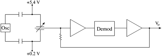
Hence the difference in capacitance is proportional to x, but only for small values of displacement. The ADXL50 uses a negative feedback control loop to make sure that the movement of the mass is kept small so that the above expression remains correct. The figure below shows a block diagram of the entire system.
Piezoelectric Sensors
- Notes below are from the lecture notes of the former CCRMA Music 252 Course
The Piezoelectric effect is an effect in which energy is converted between mechanical and electrical forms. It was discovered in the 1880's by the Curie brothers. Specifically, when a pressure (piezo means pressure in Greek) is applied to a polarized crystal, the resulting mechanical deformation results in an electrical charge. Piezoelectric microphones serve as a good example of this phenomenon. Microphones turn an acoustical pressure into a voltage. Alternatively, when an electrical charge is applied to a polarized crystal, the crystal undergoes a mechanical deformation which can in turn create an acoustical pressure. An example of this can be seen in piezoelectric speakers. (These are the cause of those annoying system beeps that are all too common in today's computers).
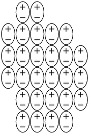
Electrets are solids which have a permanent electrical polarization. (These are basically the electrical analogs of magnets, which exhibit a permanent magnetic polarization). The figure above shows a diagram of the internal structure of a electret. In general, the alignment of the internal electric dipoles would result in a charge which would be observable on the surface of the solid. In practice, this small charge is quickly dissipated by free charges from the surrounding atmosphere which are attracted by the surface charges. Electrets are commonly used in microphones.
Permanent polarization as in the case of the electrets is also observed in crystals. In these structures, each cell of the crystal has an electric dipole, and the cells are oriented such that the electric dipoles are aligned. Again, this results in excess surface charge which attracts free charges from the surrounding atmosphere making the crystal electrically neutral. If a sufficient force is applied to the piezoelectric crystal, a deformation will take place. This deformation disrupts the orientation of the electrical dipoles and creates a situation in which the charge is not completely canceled. This results in a temporary excess of surface charge, which subsequently is manifested as a voltage which is developed across the crystal.
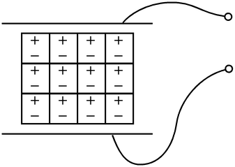
In order to utilize this physical principle to make a sensor to measure force, we must be able to measure the surface charge on the crystal. The figure above shows a common method of using a piezoelectric crystal to make a force sensor. Two metal plates are used to sandwich the crystal making a capacitor. As mentioned previously, an external force cause a deformation of the crystal results in a charge which is a function of the applied force. In its operating region, a greater force will result in more surface charge. This charge results in a voltage V=Qf/C, where Qf is the charge resulting from a force f, and C is the capacitance of the device.
In the manner described above, piezoelectric crystals act as transducers which turn force, or mechanical stress into electrical charge which in turn can be converted into a voltage. Alternatively, if one was to apply a voltage to the plates of the system described above, the resultant electric field would cause the internal electric dipoles to re-align which would cause a deformation of the material. An example of this is the fact that piezoelectric transducers find use both as speakers (voltage to mechanical) and microphones (mechanical to electrical).
