Difference between revisions of "250a Microcontroller & Sensors Lab"
(→Fading LEDs (optional)) |
(→Make a Light Dimmer) |
||
| Line 117: | Line 117: | ||
* Connect the middle pin of the potentiometer to analog input 0, the other two to +5V and ground. | * Connect the middle pin of the potentiometer to analog input 0, the other two to +5V and ground. | ||
* Through a 220Ohm resistor, connect an LED to pin 9(anode or long side to resistor, cathode to pin 9) | * Through a 220Ohm resistor, connect an LED to pin 9(anode or long side to resistor, cathode to pin 9) | ||
| − | * In the ArduinoLab patch, press the "Light Dimmer" button to preset the outputs properly. The patch expects you to connect the LED to digital pin 9 (D9) and the potentiometer to analog pin 0 (A0). | + | * In the ArduinoLab patch, press the "Light Dimmer" button to preset the outputs properly. The patch expects you to connect the LED to digital pin 9 (D9) and the potentiometer to analog pin 0 (A0). Use the PWM controls in output controls to control the lightness and dimness of the LED. |
Revision as of 18:24, 30 September 2009
Lab 2: Microcontroller and Sensors
Due on Wednesday, October 7th at 5PM
For this lab you need your MaxKit, and Max/MSP or PD on a computer.
Contents
Download software
- Make a Lab2/ folder for this lab.
- Download the following:
- Arduino Software
- If you have never used an Arduino with your computer before, you need to install the FTDI driver that comes with the Arduino software; this enables your computer to recognize the USB serial communication chip on the Arduino.
- Firmata firmware (Use Firmata-2.0beta3.zip)
- Either Maxuino or Pduino. (Do this even if you have already downloaded Maxuino or Pduino from the Firmata site, since we have included lab-specific patches.)
- Arduino Software
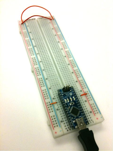
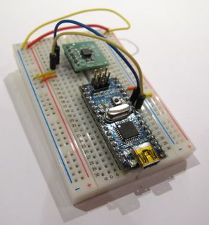
Mount your Arduino Nano on your breadboard
We will be powering the Nano and the breadboard with current from the USB port, which is good for up to 500mA of 5 V±5%-- probably enough for most input circuits, although not enough if you plan to run a lot of LEDs or motors.
- The Nano should sit at the bottom of the breadboard, so that the pins lie in rows 49-64 on either side.
- Using jumper wires, connect the row 52 pin (GND) on the left side of the Nano to the blue ground (GND) rail.
- Connect the row 52 pin (+5V) on the right side of the Nano to the red Power rail.
- Use jumper wires to connect the power and GND rails on the left side of the breadboard to the right.
Install Firmata onto your Arduino Nano
- Install the Arduino software
- Unarchive the file, and move it to your applications folder.
- Install the FTDI driver that comes with the Arduino software so that your computer will recognize the Arduino when it is plugged into the USB port.
- Unarchive the Firmata firmware that you downloaded previously.
- Use the Arduino software program to open StandardFirmata.pde, which lies inside the folder Firmata-2.0beta3:Firmata:examples:StandardFirmata. (Do NOT open the version of StandardFirmata that lies directly within the pull-down menus of the Arduino software.)
- Connect your Arduino Nano to your computer using a USB cable.
- Use Tools->Board and Tools->Serial Port to select the Arduino Nano (Atmega 328) and USBserial tty port, then hit the Play button to verify and compile the program.
- Upload the Firmata firmware to your Arduino Nano using upload button, the fourth square button from the left (the one with the sideways arrow).
- Close the Arduino program. (This is important because it frees up the USB serial port so that Max or PD can talk to the Arduino board next.)
Buttons, Switches and LEDs
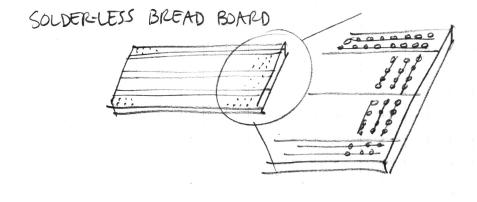
- Build the circuit that is detailed in the following figures. Use components and jumpers to construct your circuits on the solderless bread-board.
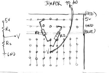
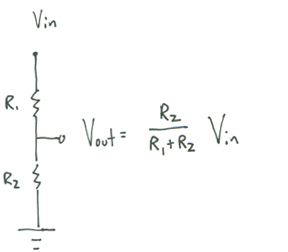
- Here's how to wire a simple 2-resistor circuit on the solderless bread-board (for example R1 = 10K, R2 = 10K):
What will A0 read?
(How do you know what resistor you have? Use the resistor calculator!)
Build the Button and LED Circuit
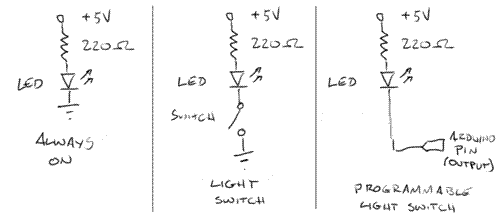
We'll start our tutorial with three simple light circuits.
- In the first one, the LED is permanently on.
- In the second, the LED only lights up when a button is pressed and a circuit is completed.
- In the third example, we'll replace the manual switch with an Arduino pin (set to output mode), so we can control the LED from our program.
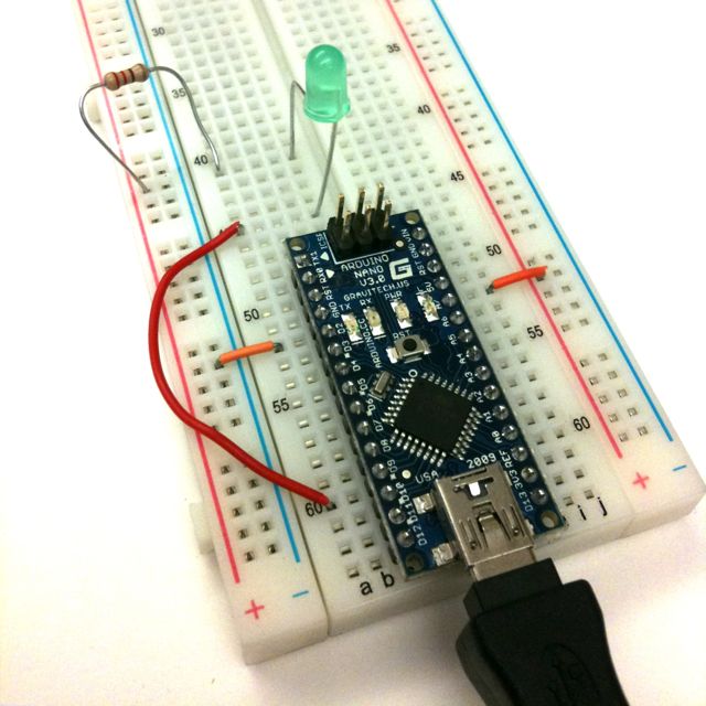
Power a LED (always on)
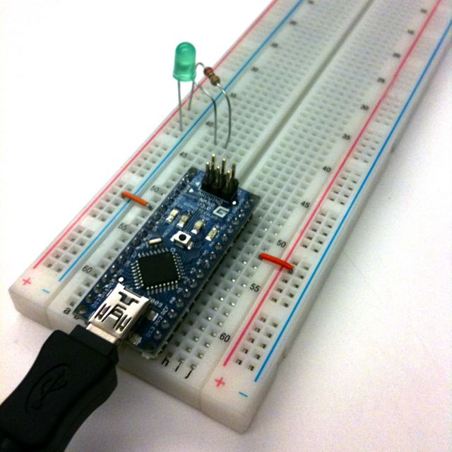
Build the following circuit on your breadboard. Use a 220Ohm resistor (red red brown gold).
Because the LED is a diode, it has a set voltage drop across the leads; exceeding this causes heat to build up and the LED to fail prematurely. So! It is always important to have a resistor in series with the LED.
Also, another consequence of the LED being a diode is that it has directionality. The longer lead, the anode, should be connected towards power; the shorter, cathode, should be connected towards ground. (In the photo, the longer lead has a bent "knee.")
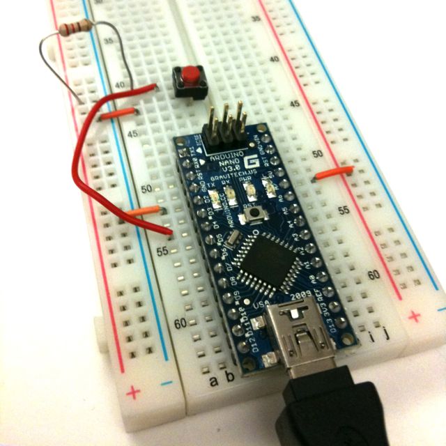
Make a light switch
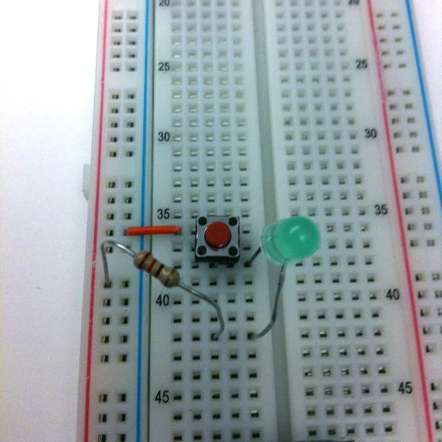
Next, we'll insert a switch into the circuit. The momentary switches in your kit are "normal open", meaning that the circuit is interrupted in the idle state, when the switch is not pressed. Pressing the switch closes the circuit until you let go again.
Use a multimeter to see what happens to the voltage on either side of the LED when you press the switch.
Toggling LED with PD or Max
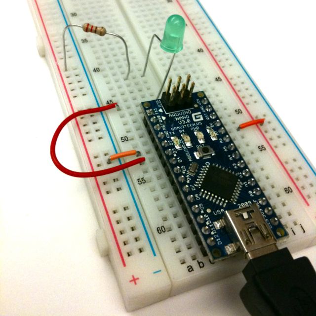
In the third example, we'll replace the manual switch with an Arduino pin (set to output mode), so we can control the LED from our program. The safe way to do this is to let the Arduino pin sink current - if we toggle the pin low, it acts as ground and current flows through the resistor and the LED as it did in the previous examples. When we take the pin high, to 5V, there is no potential difference and no current flows - the LED stays off.
- In the ArduinoLab patch, press the "toggling LED with software" button in the upper right to preset the outputs properly. The patch expects you to connect the LED to digital pin 2 (D2).
Optional: Try changing your patch so the light stays on when you press the mouse button, and stays off when you press it again. After that, change your patch so the light blinks on/off. Then, have your patch button switch the light between on and blinking.
Sensing buttons in software
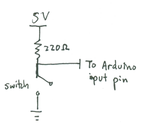
We've used code to trigger output - what about the other direction, sensing physical input in code? Just as easy. Here is a simple switch circuit:
When the switch is open, the Arduino pin (set to input mode) is pulled to 5V - in software, we'll read Arduino.HIGH. When the switch is closed, the voltage at the Arduino pin falls to 0V - in software, we'll read Arduino.LOW. The pull-up resistor is used to limit the current going through the circuit. In software, we can check the value of the pin and switch between graphics accordingly.
- In the ArduinoLab patch, press the "sensing buttons in software" button to preset the outputs properly. The patch expects you to connect the switch to digital pin 4 (D4).
Fading LEDs (optional)
What about those "breathing" LEDs on Mac Powerbooks? The fading from bright to dim and back is done using pulse-width modulation (PWM). In essence, the LED is toggled on and off rapidly, say 1000 times a second, faster than your eye can follow. The percentage of time the LED is on (the duty) controls the perceived brightness. To control an LED using PWM, you'll have to connect it to one of the pins that support PWM output - 9, 10 or 11 on the Arduino. Then write a patch that cycles the PWM values.
- In the ArduinoLab patch, press the "Fading LEDs" button to preset the outputs properly. The patch expects you to connect the LED to digital pins 9-11 (D9-11).
- In your Arduino Kit, you have a RGB LED which has four leads (it's white when not lit); it's basically like 3 LEDs sharing the same ground. Use PWM and this [pin out information] to make the LED cycle through a rainbow of colors.
Using Analog Sensors
Now we will work with the continuous input values provided by analog sensors - potentiometers, accelerometers, distance rangers, etc.
Make a Light Dimmer
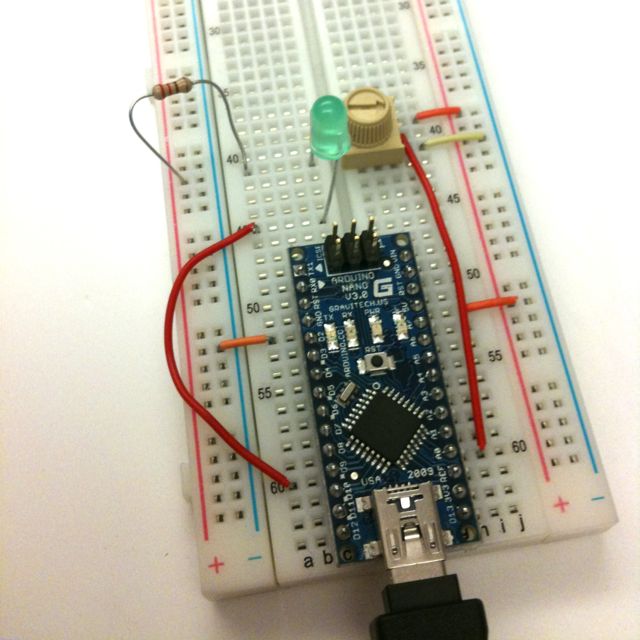
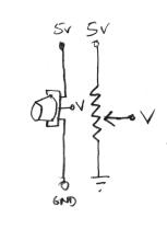
In this example we'll build a light dimmer: a knob connected to a light so that when you turn the knob, the light increases or decreases in brightness. We'll use a potentiometer. The potentiometer has three terminals - the resistance between the first and the third terminal is constant (10k Ohms in our case). The resistance between terminals 1 and 2 (and between 2 and 3) varies as you turn the shaft of the potentiometer. If you apply 5V to terminal 1, connect terminal 3 to Ground, you will get a continuously varying voltage at terminal 2 as you turn the shaft (Why that is the case will become clearer once you've learned about voltage dividers further below).
- Connect the middle pin of the potentiometer to analog input 0, the other two to +5V and ground.
- Through a 220Ohm resistor, connect an LED to pin 9(anode or long side to resistor, cathode to pin 9)
- In the ArduinoLab patch, press the "Light Dimmer" button to preset the outputs properly. The patch expects you to connect the LED to digital pin 9 (D9) and the potentiometer to analog pin 0 (A0). Use the PWM controls in output controls to control the lightness and dimness of the LED.
- Optional: hook up two LEDs, one red one green. as you turn in one direction, red gets brighter; in the other, green gets brighter. In the middle, both are off.
Drawing a graph of analog input
Let's understand better what the values are that we are reading from the analog input. To do so, we will use a slider graph to show how the analog values are changing in time.
Leave the potentiometer part of your circuit, you may take off the LED part if you want to. Use A0 or A1 to graph the analog input in the ArduinoLab patch.
Thresholding with a Range Sensor (optional)
Thresholding is the process of turning continuous data into a discrete yes/no decision.
To learn about thresholding, we'll connect the IR range sensor. The circuit is trivial: just connect red to 5V, black to ground, and yellow to analog input A0.
Take a look at the data the sensor returns with sensor_graph_02 - when the field of view of the sensor is clear (no obstacle - point it at the ceiling), it returns a low voltage. Move your hand high over the sensor, then start lowering it - you should see the output voltage rise, until you are about 4" away. The sensor has a range of operation of 4"-30".
Let's do something useful with that data. Imagine a smart cookie jar that reminds you not to snack in between meals. We could put an IR ranger into the lid. Whenever a hand comes too close, our program could play a warning sound or flash a warning light. Write a patch to manage this!
Tilt control with an Accelerometer
In this example, we'll simulate the motion of a ball on a tilting plane in software and control the tilt through a sensor. Think of it as a first step to build your own electronic game of Labyrinth. The right sensor to use is an accelerometer. Accelerometers can report on both static and dynamic acceleration -- think of static acceleration as the angle the accelerometer is held with respect to the ground (the acceleration measured here is due to gravity). Dynamic acceleration occurs when you shake the sensor.
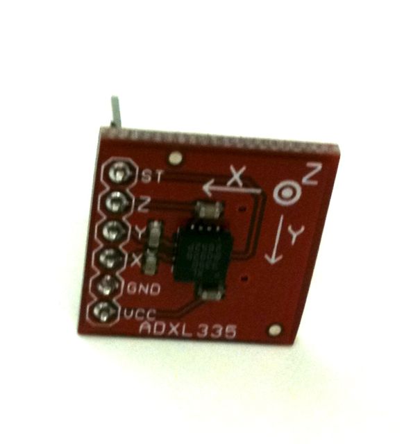
The accelerometer in your kit is a 3-axis, +-2g sensor (1g is the acceleration due to gravity). It comes with 0.1" header pins that fit into the breadboard. The connections you need to make are VCC to the 3V3 pin on the Arduino (it will be in row 62), GND to ground, and X, Y, and Z to the first three analog input pins on the Arduino board. You can ignore the ST (self test) pin.
Push the accelerometer into the breadboard and make the connections as shown:
Now, get a feel for the data the accelerometer provides. Use the Light Dimmer presets, which will track analog values on A0 and A1. Then pick up the Arduino+accelerometer board and tilt it in various directions. Start by holding it so that the accelerometer board is parallel to the ground. Find in which direction the X reading increases and decreases; do the same for the Y reading. Are the labels on the accelerometer board correct?
Voltage Dividers
In your kit, the potentiometer, IR distance ranger, and accelerometer are especially easy to work with since they directly output a changing voltage that can be read by one of Arduino's analog input pins.
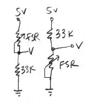
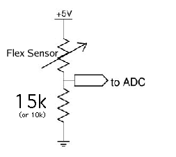
Other sensors don't give you a varying output voltage per se, but instead change their resistance. Examples in your kit are the force sensitive resistor (FSR) and the bend or flex sensor. It is easy to get a changing voltage based on a changing resistance through a voltage divider circuit(Wikipedia page). The idea is that you put two resistors in series between power and ground: one that changes resistance (your sensor), and one of a known, fixed resistance. At the point in between the two resistors, you can measure how much the voltage has dropped through the first resistor. This value changes as the ratio of resistances between variable and fixed resistors change. More formally:
- potentiometer:
- force-sensitive resistor (FSR):
Try both circuits. Test the resistance range of your sensor. If you want 2.5 volts to be the middle, make the comparison resistor (33k in the diagram) the "average" value of the FSR's resistance. Test this with a multimeter.
- Bend Sensor
Putting it all Together
- Create a patch to make sounds based on button and sensor values from the Arduino. You can try to adapt your patches from Lab 1, or come up with a new patch.
- Try to make a simple musical interaction. Think about music -
- does it have dynamics?
- can you turn the sound off?
- can it be expressive?
