Stompbox Real Sensors
Lab 2: Controlling an Effect with Real Sensors
By Edgar Berdahl
Due on Wednesday, July 20th at 9AM
* hook up button
* hook up pots
* hook up LED
* change to ring modulator
Contents
Download software
- Make a Lab2/ folder for this lab.
- Download the following:
- Arduino Software
- If you have never used an Arduino with your computer before, you need to install the FTDI driver that comes with the Arduino software; this enables your computer to recognize the USB serial communication chip on the Arduino.
- Firmata firmware (use firmata2.0beta3.zip)
- Either Maxuino or Pduino.
- Arduino Software
Power Connections
- In order to run circuits on the breadboard, you need to get power to it. The Arduino gets 5V from the USB connection, so in this section you will make the 5V accessible to the breadboard.
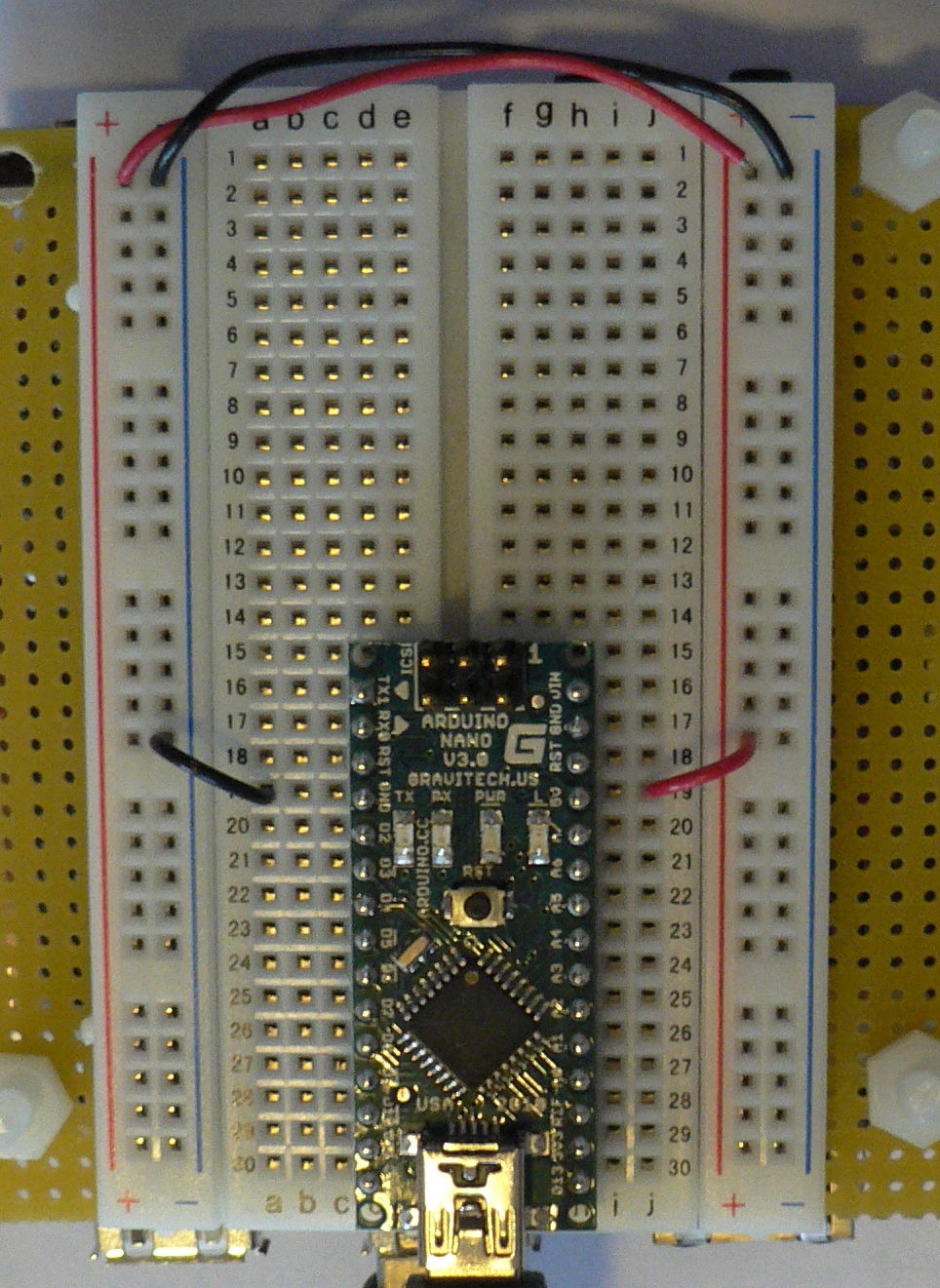
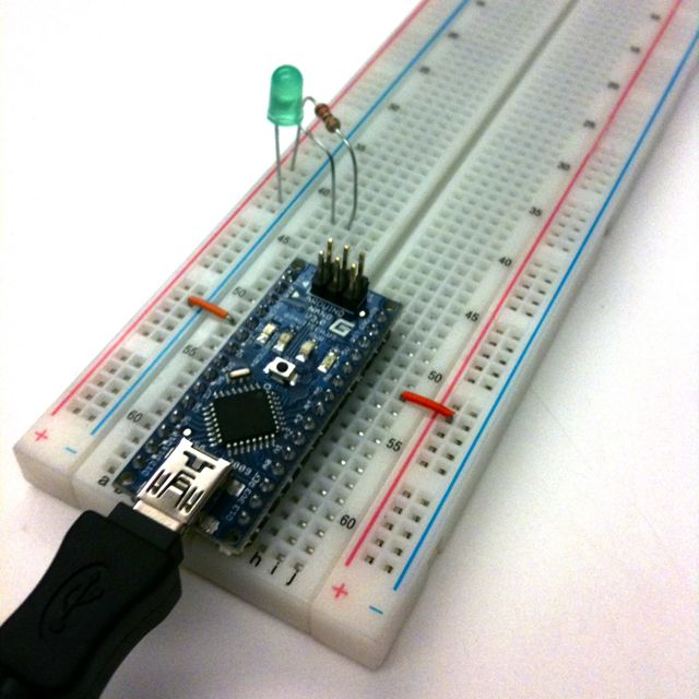
- Make sure that your Arduino is mounted at the very end of the breadboard with the higher-numbered rows, as shown in the following picture. In that case, the GND and 5V pins will end up in the 19th row. (Otherwise if your Arduino isn't mounted this way, you simply won't be able to rely on the row numbers, but you can still figure out how to wire things up!)
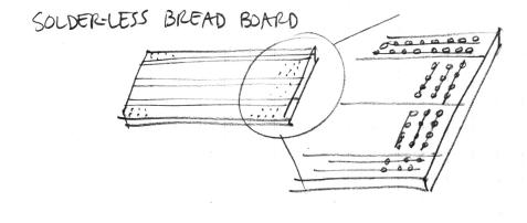
- Recall first that that holes in the solderless bread board are wired together as shown:
- Using short jumpers, connect the GND row to the blue "GND" bus on the breadboard, and connect the 5V row to the red "power" bus on the breadboard.
- Connect the "GND" and "power" busses from both sides of the breadboard together as shown.
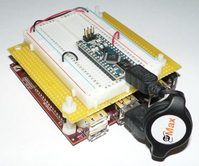
Viewed from further away, your breadboard should now look like the following:
First Circuit: Potentiometer
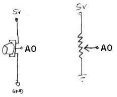
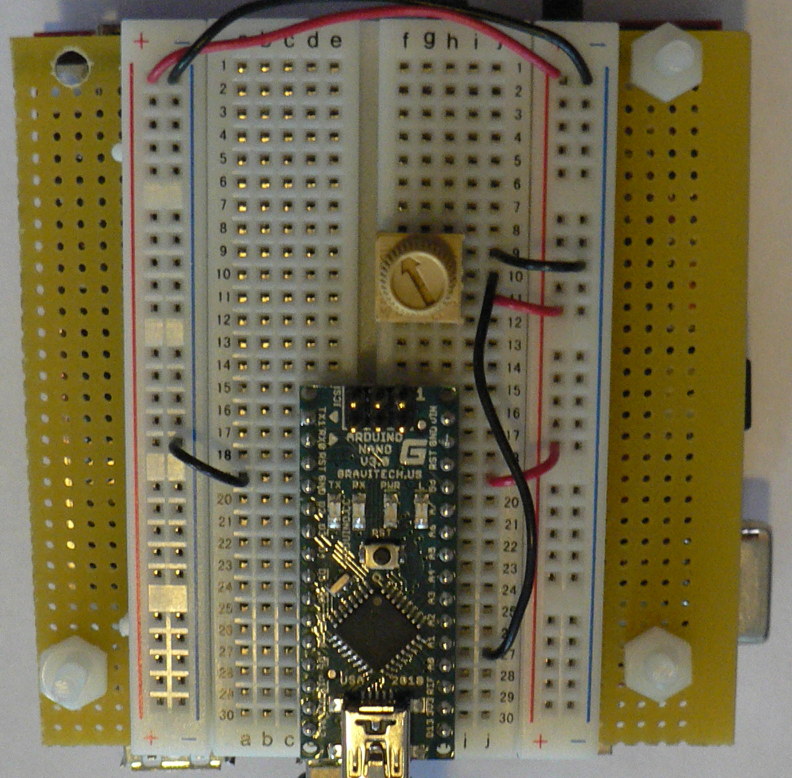
Now you will build the following voltage divider circuit, to connect one potentiometer to analog input A0.
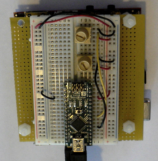
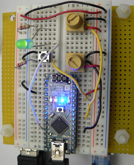
For some help on placing the wires, please see the following picture. In order to ensure the correct orientation, ensure that the text on the potentiometer is facing away from the Arduino (see also oblique picture in next section).
Add A Second Potentiometer
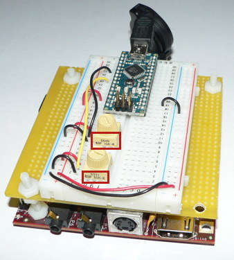
Now connect a second potentiometer to analog input A3 using the same voltage divider circuit.
Again, ensure that the text on the potentiometer is facing *away* from the Arduino (see the red boxes in the following figure):
Add A Button
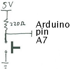
Most stomp boxes have a button, so we include that as well according to the following circuit:
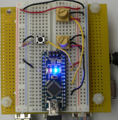
The corresponding picture of the bread board is shown below:
Add An LED
Finally, we add an LED for fun and to help with debugging.
Build the Button and LED Circuit
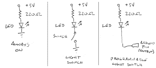
We'll start our tutorial with three simple light circuits.
- In the first one, the LED is permanently on.
- In the second, the LED only lights up when a button is pressed and a circuit is completed.
- In the third example, we'll replace the manual switch with an Arduino pin (set to output mode), so we can control the LED from our program.
Power a LED (always on)
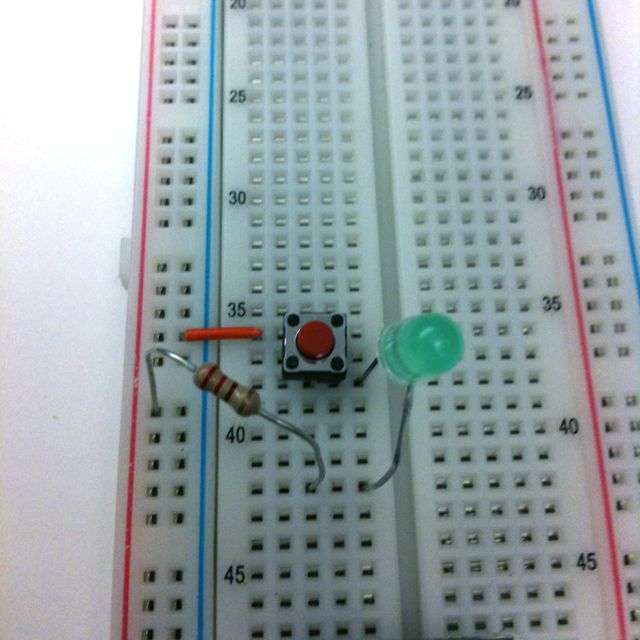
Build the following circuit on your breadboard. Use a 220Ohm resistor (red red brown gold).
Because the LED is a diode, it has a set voltage drop across the leads; exceeding this causes heat to build up and the LED to fail prematurely. So! It is always important to have a resistor in series with the LED.
Also, another consequence of the LED being a diode is that it has directionality. The longer lead, the anode, should be connected towards power; the shorter, cathode, should be connected towards ground. (In the photo, the longer lead has a bent "knee.")
Make a light switch
Next, we'll insert a switch into the circuit. The momentary switches in your kit are "normal open", meaning that the circuit is interrupted in the idle state, when the switch is not pressed. Pressing the switch closes the circuit until you let go again.
Use a multimeter to see what happens to the voltage on either side of the LED when you press the switch.
Putting it all Together
- Create a patch to make sounds based on button and sensor values from the Arduino. You can try to adapt your patches from Lab 1, or come up with a new patch.
- Try to make a simple musical interaction. Think about music -
- does it have dynamics?
- can you turn the sound off?
- can it be expressive?
Appendix: Install Firmata onto your Arduino Nano
- Install the Arduino software
- Unarchive the file, and move it to your applications folder.
- Install the FTDI driver that comes with the Arduino software so that your computer will recognize the Arduino when it is plugged into the USB port.
- Unarchive the Firmata firmware that you downloaded previously.
- Connect your Arduino Nano to your computer using a USB cable.
- Open StandardFirmata the Arduino software pull-down menus Examples|Firmata.
- Use Tools->Board and Tools->Serial Port to select the Arduino Nano (Atmega 328) and USBserial tty port, then hit the Play button to verify and compile the program.
- Upload the Firmata firmware to your Arduino Nano using upload button, the fourth square button from the left (the one with the sideways arrow).
- Close the Arduino program. (This is important because it frees up the USB serial port so that Max or PD can talk to the Arduino board next.)
Important Note!!
Some of the text and images here was taken from prior laboratory exercises for the course Music 250A. We regret that we do not know who contributed these elements, but these people are likely to include Wendy Ju, Bill Verplank, Michael Gurevich, and more.
