Tangible Embedded Linux Old
These instructions have most recently been heavily edited by Edgar Berdahl
(Some portions of the teaching materials may have been contributed by other authors such as Wendy Ju, Bill Verplank, Michael Gurevich, Spencer Salazar, Matt Wright, etc.)
This workshop consists of a condensed version of the material from labs 1 and 2 for the course Music 250A at Stanford University. For this workshop you need your Satellite CCRMA kit, a laptop computer with Ethernet adaptor to program it, and some headphones with a mini 1/8" (2.54mm) stereo jack.
You are also invited to bring the following optional items, but they are by no means required:
- Some of your favorite breadboardable sensors and LEDs.
- A set of small, battery powered speakers with 1/8" (2.54mm) jack.
- A pico projector with cable to HDMI connector.
Prior to coming to the workshop, you may wish to read more about Satellite CCRMA, Pure Data, Raspberry Pi, or the Arduino Nano.
Introductions
- Participants explain their backgrounds and what they would like to get out of the studio.
- Show some videos of prior projects
- Construct Satellite CCRMA kits
Powering Up For The First Time
Plug the Ethernet port of the Satellite CCRMA into your laptop. Then use the USB micro cable to connect your laptop to the Raspberry Pi--this provides the power. You should see some lights turn on, flickering every now and then. This means that Satellite CCRMA is booting up.
Connect To Satellite CCRMA
In order to see what your Satellite CCRMA kit is doing and program it, you need to log in to it. To do so, follow these instructions.
After you login, you will see the prompt ccrma@satellite:~$ This means that you are logged into a computer named "satellite" as the user "ccrma", and you are currently in the directory ~, which is the shortcut for your home directory.
Stop Default Patch and Run Pd
- In order to be able to hear audio, you will need to plug a pair of ear buds, headphones, or loudspeakers into the 1/8" (2.54mm) jack labeled AUDIO OUT on the Raspberry Pi. Be careful when plugging the headphones in and not to pull too hard on the headphone cable!
- A default pd patch starts running automatically when your kit finishes booting up. If your kit is configured correctly, the only evidence you will have of this is some sound in the headphones (you might have to touch the A0 pin on the Arduino with your finger to hear the sound). To stop the default patch, run the command
stop-default
When you run this command, you will observe that the sound in the headphones stops.
Remember that each time you boot up your kit and want to edit your patch, you should stop the default patch from running by using the command stop-default
- Start pd now again with the following command:
pd &
This time the graphical user interface (GUI) for pd should also start.
- To start audio, click on the Compute audio checkbox.
- Now to test audio, go to the media pull-down menu and choose Test Audio and MIDI. If you still do not here any sound, then probably you missed one of the steps so far. If you look at the messages in the main pd window, you might find a clue.
- Once you have audio working, close the window test audio and MIDI window.
Learn A Little More About Pd
If you get stuck at some point while learning about pd, remember that you can right-click on an object to get help information about the object.
- The patch ~/pd/examples/just-play-WAV-files/play-WAV-file.pd shows the easiest way to play a WAV file.
- Look at the pd lecture patches stored in ~/pd/pd-lecture (For example, see the patch 4_algorithmic_music.pd. Make sure that audio is on and increase the volume from zero in the patch.)
- By default, the patch ~/on-startup/default-patch.pd runs right when the kit finishes booting up. Open this patch manually from within pd.
- Look at the lower, right-hand corner of the patch. You will see that this patch automatically enables audio 8 seconds (i.e. 8000 milliseconds) after the patch is opened.
- Now, if you touch the A0 pin or the Arduino with your hand, you should be able to hear the sound of a windy day. (If you still don't hear anything, try touching a grounded object with your other hand.)
- The patch works by filtering white noise (from noise~) with a bandpass filter with a high quality factor. The output of the highpass filter is then scaled by a gain controlled from A0.
- Look inside the subpatches that are named pd <name> by double-clicking on them.
- You will notice that this kind of sensing is not very reliable. In the next parts of the lab, you will learn how to connect a sensor to A0 to improve the quality of the sensing.
Routing Power On The Breadboard
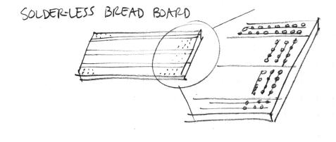
- Remind yourself about how the sockets on the breadboard are wired together:
- Now you are going to start putting jumper wires into your breadboard. Try to be careful to build the circuit correctly. (If you create a short circuit (one kind of wiring mistake), then the lights will instantly all go off on the Arduino. If this happens, please try to undo the short circuit right away.)
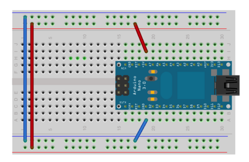
- Now connect jumper wires as shown in the image below so that the upper and lower long columns can serve as a power supply for your future circuits.
- Connect a short jumper from the GND pin of the Arduino to the blue column.
- Connect a short jumper from the 5V pin of the Arduino to the red column.
- Finally, use two longer jumpers to connect together the blue columns and the red columns as shown below:
- Check your wires again to make sure that you did it correctly!
Connect Your Analog Sensor To Pin A0
Each participant should have one analog sensor in his or her kit. Optionally go to one of the following links to learn more about electronics or sensors. Ask one of the staff for help if you feel uncomfortable with electronics. We will help you.
Force-Sensing Resistor
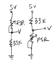
If you have a force-sensing resistor, you can hook it up to an analog input of the Arduino by building a voltage divider out of it with a 33k fixed resistor. The idea is that you put two resistors in series between power and ground: one that changes resistance (your sensor), and one of a known, fixed resistance. At the point in between the two resistors, you can measure how much the voltage has dropped through the first resistor. This value changes as the ratio of resistances between variable and fixed resistors change.
- force-sensitive resistor (FSR):
Soft-Pot
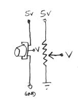
- If instead you have a soft-pot or a standard potentiometer, then you can wire it up this way:
Range Sensor
- If you have an infra-red range sensor, then connect the black wire to ground, the red wire to 5V (power), and connect the other wire directly to an analog input on the Arduino.
Optimizing The Patch
You might want to speed up the lowpass filter so that your pd patch responds more quickly to your sensor. To do so, go inside the pd lowpass subpatch and increase the cutoff frequency of onepole~ from 0.4 Hz to something more like 10 Hz.
Make Your Tangible Embedded Prototype
- Now use these tools to make a completed prototype by editing ~/on-startup/default-patch.pd
- This way, each time you power up your kit (whether or not a laptop is connected), it will run your modified patch.
- For additional exercises or things to think about, you may want to look at the Further Reading or down below also.
Troubleshooting
- Note that only one program or patch can use the Arduino at the same time.
- If you are having troubles, make sure that you do not have multiple copies of pd running and/or that you only have one patch open that access the Arduino.
Appendix A. Transferring Files To and From Your Kit
- Download CyberDuck to your laptop to make it easy to transfer files back and forth from your kit.
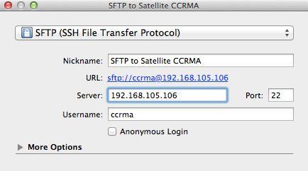
- Start CyberDuck on your laptop, and then create the following new bookmark:
- Once you have finished entering the text, close the bookmark window.
- Then you can use CyberDuck to connect to your Satellite CCRMA kit by double clicking on the SFTP to Satellite CCRMA bookmark.
- After you enter the password temppwd, CyberDuck will connect and open window to open up showing the files in the /home/ccrma home directory on your kit.
- You can drag and drop files from here to move them back and forth.
- If you move WAV files to your kit, please remember that the default sampling rate for pd is 22kHz, so you may want to resample them first.
Appendix B. Learn A Lot More About Pd
- Here are some lists of pd objects that you can use to discover new object names: http://protman.com/content/list-puredata-objects-and-extended-objects http://www.umatic.nl/workshop/objects.txt
- Go to the Help pull-down menu, choose Browser, go into Pure Data (near the top), and then look through the demonstration pd patches that are organized into chapters.
- For even more further learning, see the labs from the Music 250A course, which are stored in ~/pd/labs-Music-250a-2012
Advanced demo patches for users who have a monitor or pico projector connected:
- The pd patches in ~/pd/examples/SimpleGraphicsOSC can be used to send OSC messages to the SimpleGraphics executable to render hardware-accelerated graphics.
- OR, the patch ~/pd/examples/just-play-video/trigger-omxplayer.pd can be used to trigger the playback of H.264 or MPEG2-encoded video clips.
Epilogue I. Protect The Flash Memory
- Once you are completely done making your prototype, then run the command disable-flash-writes
- After this, any changes you make to your memory card will not be persistent. This means that you can power down your kit at any time without any warning (for instance if it is in a museum), and you do not have to worry about the disk integrity (as you would with your laptop for instance if its power were suddenly cut). If you change your mind later, you can always run the command enable-flash-writes to undo this step.
- (If you prefer not to protect the memory of your kit, then when you are finished and before you power it down, kindly remember to run the command sudo halt, enter the password, and then wait 20 seconds before removing the power.)
Epilogue II. End Of Workshop
- We will evaluate each others’ interactions in pairs and then share the results in a concluding roundtable discussion. There has been some discussion about also presenting to a wider audience.
- Please don't do this during the workshop unless you discuss it with me first: At home, you can setup your kit to connect directly to an Internet router (warning -- this method is still undergoing testing):
- First login using the usual method. Then run the command ethernet-use-dhcp
- Follow the instructions then for shutting down your kit.
- Disconnect your kit from your laptop and connect it directly to your home router. Then power up your Satellite CCRMA kit again.
- Now you can hopefully login from any other computer at home using the command ssh -XY ccrma@satellite.local"
- If that doesn't work, you can either plug in a monitor and see what IP address CCRMA Satellite reports it has at the end of boot, or if you have a Mac or Linux, you can run the following command in linux to help you determine what IP address your Satellite CCRMA kit may have been assigned by the local router. The following version scans the addresses 192.168.1.1 through 192.168.1.254, but edit as necessary for your home network: for ip in 192.168.1.{1..254}; do ping -t 1 $ip > /dev/null && echo "${ip} is up"; done
- Now, after you are logged into your kit, verify that you can access the Internet by running ping yahoo.com
- If you still cannot access the Internet from your kit, then find out the IP address of the name server for your network and then set it using set-name-server <IP_address_of_correct_name_server>
- At this point, you may be interested in other advanced features, so see a list of other useful commands.
- Assuming you are able to login again, you could change the configuration back to the way we had it during the workshop by running ethernet-use-staticIP
- Finally, for more information, please see the Satellite CCRMA main web page.
