Stompbox Real Sensors 2013
Lab 2: Controlling an Effect with Real Sensors
Designed by Edgar Berdahl
Due on Wednesday at 9AM
Log In
Log in to your kit as usual.
Don't forget to run sudo pkill pd to stop any default patch from running.
Appendix: Install Stompbox Firmware onto your Arduino Nano
- Use the USB cable to plug the Arduino Nano into the Beagle Board.
- From the terminal, run the command arduino & to start up the Arduino software.
- From the menu Tools|Board choose Arduino Duemilanove or Nano w/ 328
- From the menu Tools|Serial port choose /dev/ttyUSB0
- Open the sketch /home/ccrma/pd/stompbox/startup-stompbox/FirmataAllInputs_ExceptOnePWMOut/FirmataAllInputs_ExceptOnePWMOut.pde
- Press the Verify button.
- Check the Arduino messages window to make sure that the code successfully compiled. (Usually, it will say something like Done compiling and Binary sketch size ...)
- Press the Upload button (looks like an arrow pointing to the right) to install the firmware on the Arduino.
- Check the Arduino messages window to make sure that you have successfully uploaded the firmware.
Power Connections
- In order to run circuits on the breadboard, you need to get power to it. The Arduino gets 5V from the USB connection, so in this section you will make the 5V accessible to the breadboard.
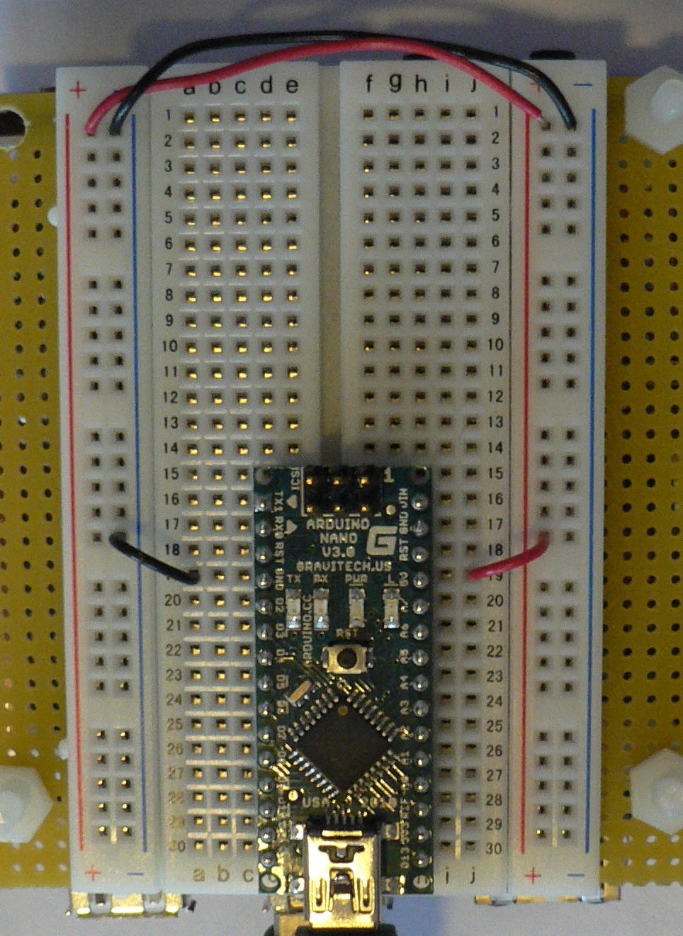
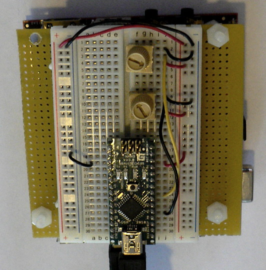
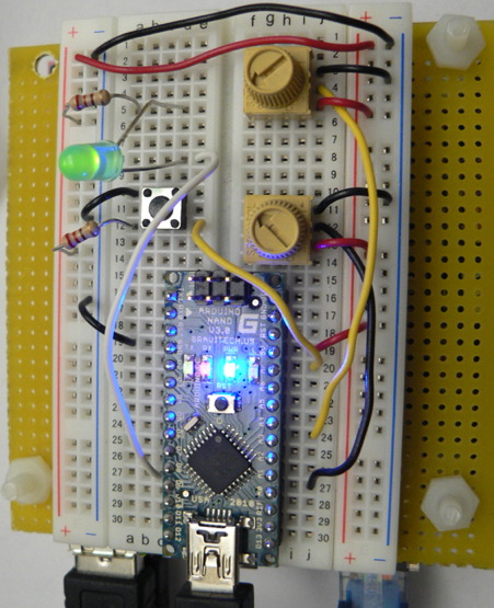
- Make sure that your Arduino is mounted at the very end of the breadboard with the higher-numbered rows, as shown in the following picture. In that case, the GND and 5V pins will end up in the 19th row. (Otherwise if your Arduino isn't mounted this way, you simply won't be able to rely on the row numbers, but you can still figure out how to wire things up!)
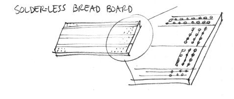
- Recall first that that holes in the solderless bread board are wired together as shown:
- Using short jumpers, connect the GND row to the blue "GND" bus on the breadboard, and connect the 5V row to the red "power" bus on the breadboard.
- Connect the "GND" and "power" busses from both sides of the breadboard together as shown.
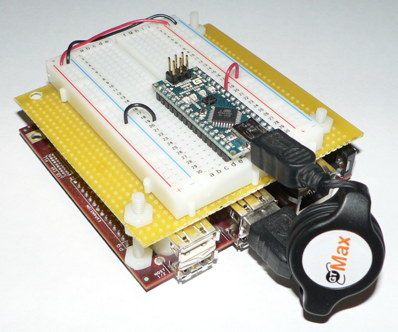
Viewed from further away, your breadboard should now look like the following:
First Circuit: Potentiometer
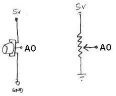
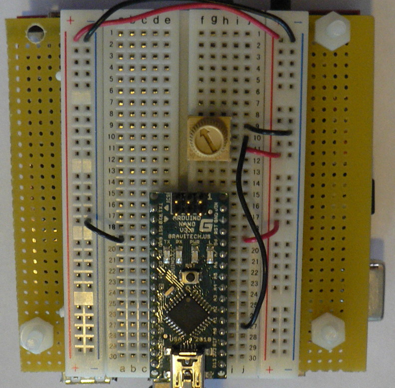
Now you will build the following voltage divider circuit, to connect one potentiometer to analog input A0.
For some help on placing the wires, please see the following picture. In order to ensure the correct orientation, ensure that the text on the potentiometer is facing away from the Arduino (see also oblique picture in next section).
Add A Second Potentiometer
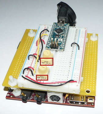
Now connect a second potentiometer to analog input A3 using the same voltage divider circuit.
Again, ensure that the text on the potentiometer is facing *away* from the Arduino (see the red boxes in the following figure):
Add A Button
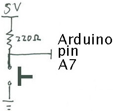
Most stomp boxes have a button, so we include that as well according to the following circuit:
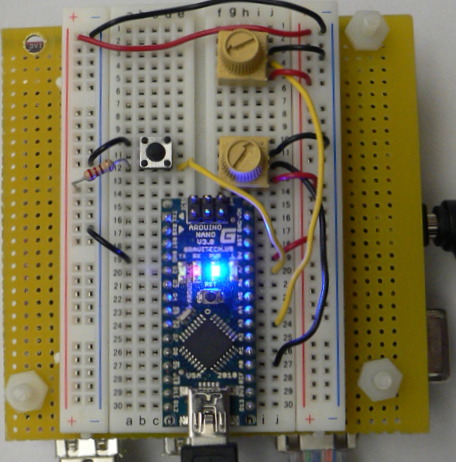
The corresponding picture of the bread board is shown below:
Add An LED
Finally, we add a light-emitting diode (LED) for fun and to help with debugging. Recall that current can only flow in one direction through a diode. One good trick to remember for LEDs is that the longer leg (the anode) points toward the power supply. The 220 Ohm resistor limits the amount of current that can flow through the LED.
Test The Tremolo Effect
Now you will test a very simple tremolo effect.
- Connect headphones or some small loudspeakers to the audio out jack on the Beagle Board. (It is the one closer to the middle of the board.)
- Connect an input audio source, such as a small MP3 player or instrument the audio output of the jack on the Beagle Board.
- Start pd by running pd &
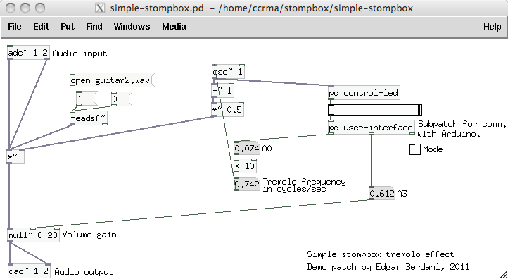
- Open the patch ~/pd/stompbox/startup-stompbox/startup-stompbox.pd using the File|Open menu option.
- Start audio signal computation by checking the compute audio button in the main pd window.
- The oscillator's output should be displayed by the horizontal slider and LED in real time. (If not, please go back and make sure you carried out all of the previous instructions.)
- Verify that turning the potentiometer connected to input pin A3 on the Arduino adjusts the value A3 shown in the main patch window. This should also change the output volume of the effect.
- Verify that turning the potentiometer connected to input pin A0 on the Arduino adjusts the oscillator frequency.
- Look inside the subpatch pd user-interface, which access the Arduino, and figure out how you could access data coming from the other analog inputs. Would you need to add an outlet to the subpatch?
- Verify that when you press the button, the mode checkbox changes its state. Modify the effect to so that the mode checkbox implements a bypass switch. We will ask some volunteers in class the following morning to explain how to do this.
Build A Wah Effect
- Open the file wahwah.pd and play around with the filter parameters for a while.
- Note that there is no way to adjust the parameters without a graphical user interface. Take the pd user-interface object from the previous patch, and modify it to control the Wah effect parameters in a sensible way. Get ready to rock out!
- Optional: Find a potentiometer that can be adjusted with your foot (e.g. talk to Edgar) and wire it into the circuit to make the wah effect control complete!
- Alternative optional activity: Look inside how the filters are adjusted and make your own filter design.
Optional: Build A New Effect
- Build a new effect whose parameters are adjustable by the potentiometers and button. We will ask for volunteers to demonstrate this the following morning in class. You can build on what you did in lab 1 if you like.
- Think about the result
- do the controls allow the entire space of parameters to be explored?
- is it easy to choose any desired set of parameters?
- does the effect sound good?
- does it have dynamics?
- would you want to use it live?
- If not, what is missing still?
Important Note
Some small amount of the text and images here was taken from prior laboratory exercises for the course Music 250A. We regret that we do not know who contributed these elements, but these people are likely to include Wendy Ju, Bill Verplank, Michael Gurevich, and possibly more.
