7745 Analog Sensing Lab
This lab most recently revamped by Edgar Berdahl and Wendy Ju. Chris Carlson, possibly Bill Verplank, and others have likely contributed.
For this lab you need your Satellite CCRMA kit, a laptop computer with Ethernet adaptor to program it, and some headphones with a mini 1/8" (2.54mm) stereo jack.
You are also invited to bring the following optional items, but they are by no means required:
- Some of your favorite breadboardable sensors and LEDs.
- Your powered loudspeaker.
Make A Sandwich
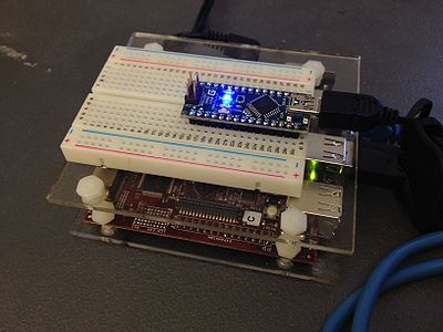
- Make a sandwich using the acrylic so that the Raspberry Pi sits on the bottom level and the breadboard sits on the top level (see below).
- When placing the breadboard, make sure that the higher numbered rows are facing the USB and ethernet ports of the Raspberry Pi.
- It may fit better if you use three nylon screws instead of four when making the sandwich.
- Insert your Arduino Nano into the breadboard all the way at the end toward the higher numbered rows and seated roughly in the middle (see below).
(Board shown underneath is the Beagle Board xM instead of the Raspberry Pi, but the idea is the same)
Power Up and Prepare Arduino
- Use the same procedure as described before to power up Satellite CCRMA and login as the user ccrma with the password temppwd.
- As always start by running the following command to stop the default pd patch from running
stop-default
- Then start pd by executing
pd &
Routing Power On The Breadboard
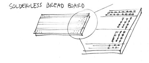
- Remind yourself about how the sockets on the breadboard are wired together:
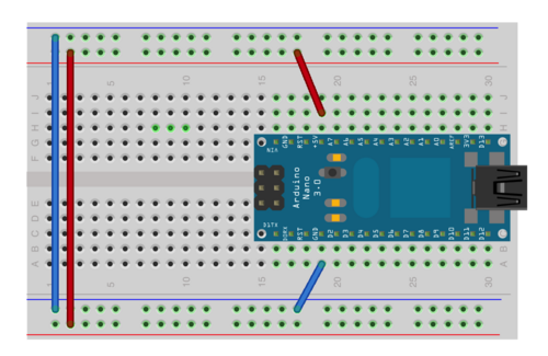
- Now connect jumper wires as shown in the image below so that the upper and lower long columns can serve as a power supply for your future circuits.
- Connect a short jumper from the GND pin of the Arduino to the blue column.
- Connect a short jumper from the 5V pin of the Arduino to the red column.
- Finally, use two longer jumpers to connect together the blue columns and the red columns as shown below:
- Check your wires now to make sure that you did it correctly!
- Now plug the retractable USB cable to plug the Arduino into one of the USB ports of the Raspberry Pi. You should see the blue light come on on the Arduino. (If you don't or you see any smoke, you have a short circuit! In other words, somehow you connected the wires together incorrectly, effectively connecting the 5V and the GND pins of the Arduino together. Unplug the USB cable again immediately and fix the circuit! Short circuits are big no-nos because they can (and often do!) destroy the Arduino.)
Analog Circuits
Now we will work with the continuous input values provided by analog sensors - potentiometers, accelerometers, distance rangers, etc
Voltage Divider Circuit
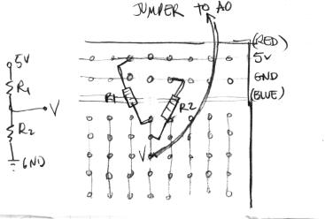
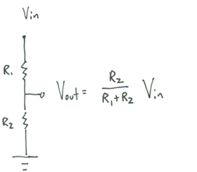
- Here's how to wire a simple voltage divider circuit using two fixed resistors on the solderless breadboard (for example R1 = 10K, R2 = 10K):
Use the voltage divider equation to calculate hypothetically what A0 should be.
Optional: Use the digital multimeter to check the voltage at A0. Set it to the direct current voltage "DVC" scale at 20V. On the multimeter, connect the black probe to COM and the red probe to V-Ohm-mA. Connect the other end of the black probe to ground and the red probe to the A0 wire. Also optional: Use the digital multimeter to find out what the "5V" supply actually is.
First Analog Sensor Circuit: Potentiometer
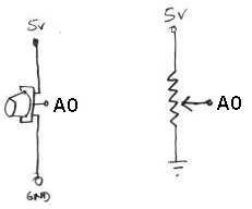
- Connect a potentiometer up to analog input A0 of the Arduino. Here is the circuit:
- Then open the pd patch ~/pd/labs-Music-250a-2012/lab2/
- Read the messages in the pd window and make sure that it was able to open the device on /dev/ttyUSB0 (this is the Arduino -- it's showing up as the 0th serial device).
- Enable the input for analog in 0 by checking the appropriate checkbox.
- Then, when you turn the knob clockwise, the a0 value shown in pd should increase.
- How can you change the circuit so that turning the knob clockwise decreases the a0 value shown in pd?
Other Voltage Dividers
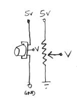
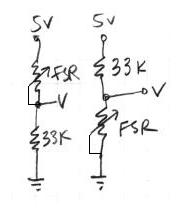
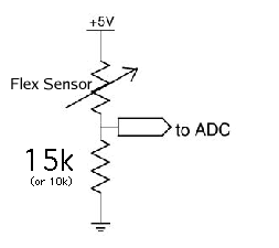
The circuit you just used for the potentiometer was a voltage divider circuit in which the potentiometer serves as two resistors. Other resistive sensors only have two wires, so to build a voltage divider with them, you need to combine them with a second, fixed resistor. Examples in your kit are the force sensitive resistor (FSR) and the bend or flex sensor. The idea is that you put two resistors in series between power and ground: one that changes resistance (your sensor), and one of a known, fixed resistance. At the point in between the two resistors, you can measure how much the voltage has dropped through the first resistor. This value changes as the ratio of resistances between variable and fixed resistors change. More formally:
- potentiometer:
- force-sensitive resistor (FSR):
Try both circuits. Test the resistance range of your sensor. If you want 2.5 volts to be the middle, make the comparison resistor (33k in the diagram) the "average" value of the FSR's resistance. Test this with a multimeter.
- Bend Sensor
Tilt control with an Accelerometer (Optional)
The accelerometer doesn't work using a voltage divider, but it does produce an output voltage that can be connected directly to an analog input of the Arduino.
In this example, we'll simulate the motion of a ball on a tilting plane in software and control the tilt through a sensor. Think of it as a first step to build your own electronic game of Labyrinth. The right sensor to use is an accelerometer. Accelerometers can report on both static and dynamic acceleration -- think of static acceleration as the angle the accelerometer is held with respect to the ground (the acceleration measured here is due to gravity). Dynamic acceleration occurs when you shake the sensor.
The accelerometer in your kit is a 3-axis, +/- 1.5-6g accelerometer sensor (1g is the acceleration due to gravity). You will have to solder on 0.1" header pins to fit this into the breadboard. The connections you need to make are Vin to 5V power from the Arduino , G to ground, and Xo, Yo & Zo to the first three analog input pins on the Arduino board. By default, the acceleration range is set to +/- 1.5g; you could solder on the gsel jumpers if you want less sensitive/greater range with +/- 6g.
Now, get a feel for the data the accelerometer provides. Use the Light Dimmer presets, which will track analog values on A0 and A1. Then pick up the Arduino+accelerometer board and tilt it in various directions. Start by holding it so that the accelerometer board is parallel to the ground. Find in which direction the X reading increases and decreases; do the same for the Y reading.
Next, change the PD patch so that you can also read the Z axis of the accelerometer.
Putting it all Together
- Create a patch to make sounds based on button and sensor values from the Arduino. You can try to adapt your patches from Lab 1, or come up with a new patch. Try to make the sound good!
- Make a simple musical interaction. Think about music -
- does it have dynamics?
- can you turn the sound off?
- can it be expressive?
