7745 Breadboarding lab 2020
Breadboarding lab
Designed by Edgar Berdahl
For this lab you need your Satellite CCRMA kit, a laptop computer with Ethernet adaptor to program it, and some headphones with a mini 1/8" (2.54mm) stereo jack.
In this lab, the images will show the Beagle Board xM instead of the Raspberry Pi, but actually all of the wiring is essentially the same. Today, we won't be "building a sandwich" with the Raspberry Pi and Arduino; however, we may do that at a future time if you're trying to make your kit smaller!
Power Connections
- In order to run circuits on the breadboard, you need to get power to it. The Arduino gets 5V from the USB connection, so in this section you will make the 5V accessible to the breadboard.
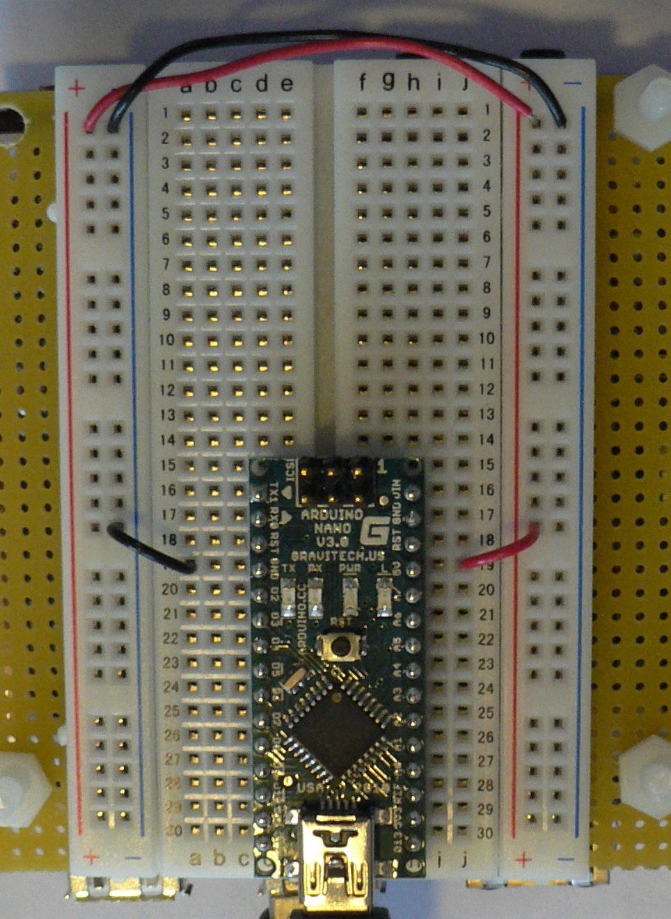
- Make sure that your Arduino is mounted at the very end of the breadboard with the higher-numbered rows, as shown in the following picture. In that case, the GND and 5V pins will end up in the 19th row. (Otherwise if your Arduino isn't mounted this way, you simply won't be able to rely on the row numbers, but you can still figure out how to wire things up!)
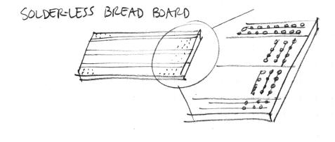
- Recall first that that holes in the solderless bread board are wired together as shown:
- Using short jumpers, connect the GND row to the blue "GND" bus on the breadboard, and connect the 5V row to the red "power" bus on the breadboard.
- Connect the "GND" and "power" busses from both sides of the breadboard together as shown.
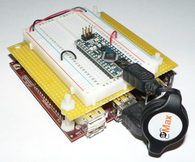
Viewed from further away, your breadboard should now look like the following:
First Circuit: Potentiometer
- Use the same procedure as before to power up Satellite CCRMA and login as the user ccrma with the password temppwd.
- Don't forget to stop the default patch from running by executing the command
stop-default
- Start pd using the following command
pd &
- Open the pd patch
~/pd/labs-2016-Music-7745/5.breadboarding-sensors/test-Arduino-only.pd
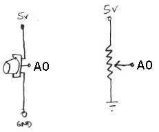
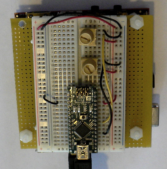
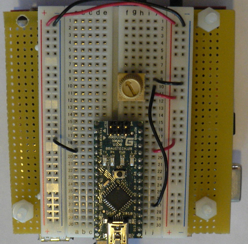
- Now you will build the following voltage divider circuit, to connect one potentiometer to analog input A0.
For some help on placing the wires, please see the following picture. In order to ensure the correct orientation, ensure that the text on the potentiometer is facing away from the Arduino (see also oblique picture in next section).
Add A Second Potentiometer
Now connect a second potentiometer to analog input A3 using the same voltage divider circuit.
Other Voltage Dividers
The circuit you just used for the potentiometer was a voltage divider circuit in which the potentiometer serves as two resistors. Other resistive sensors only have two wires, so to build a voltage divider with them, you need to combine them with a second, fixed resistor. Examples in your kit are the force sensitive resistor (FSR) and the bend or flex sensor. The idea is that you put two resistors in series between power and ground: one that changes resistance (your sensor), and one of a known, fixed resistance. At the point in between the two resistors, you can measure how much the voltage has dropped through the first resistor. This value changes as the ratio of resistances between variable and fixed resistors change.
See the page on Sensors for more info!
Troubleshooting
- Only one pd patch can access the Arduino at a time. If you have two patches open that are trying to access it, then the sensor values delivered in pd won't make any sense.
- For power users only: Whenever you upload new firmware to the Arduino, the serial port needs to be free. This means that you can't have any pd patches open that are communicating with the Arduino while uploading new firmware.
Conclusions
Read more about other sensors in the lecture notes.
Evaluation
- Think about the result
- do the controls allow the entire space of parameters to be explored?
- is it easy to choose any desired set of parameters?
- does the effect sound good?
- does it have dynamics?
- would you want to use it live?
- If not, what is missing still?
More Reading About Arduino
This OPTIONAL section is for power users only.
- See which devices are attached to Linux by running the command following command. They will appear the be files. Wow, there are so many!
ls /dev
- To list only the serial interface devices type
ls /dev/tty*
- Now unplug the Arduino from the Raspberry Pi using the USB cable. The lights on the Arduino board should turn off.
- Now run
ls /dev/tty*
again, and you should now see that the device /dev/ttyUSB0 is gone, which represented the Arduino Nano when it was plugged in.
Troubleshooting: If you didn't see /dev/ttyUSB0 when the Arduino was plugged in, then try rebooting using sudo reboot to see if that fixes this problem. (If you reboot, this will take about 45 seconds, and you will have to login again using ssh. If that doesn't work, come talk to us. If you are a Linux pro, you can try to debug the problem yourself by typing dmesg and looking at the result.)
- By the way, here is how we installed the Arduino firmware on the Arduino before the start of this lab (and the previous one). Plug the Arduino back into the Raspberry Pi and start the Arduino software in the terminal by typing
arduino &
- Open StandardFirmata from the Arduino software pull-down menus File|Examples|Firmata. Look at the program. This is what will control the Arduino.
- Select Arduino Nano w/ ATMega328 under Tools->Board and /dev/ttyUSB0 under Tools->Serial Port. Then hit the Play button to verify and compile the program.
- Upload the Firmata firmware to your Arduino Nano using upload button, the second square button from the left (the one with the sideways arrow).
- Close the Arduino program by closing all of the Arduino windows. (This is important because it frees up the USB serial port so that Pd can talk to the Arduino board later.)
