Accelerometers
We have used many different accelerometer parts, so I am collecting our notes on them here. - Edgar
Tilt control with an Accelerometer (Optional)
In this example, we'll simulate the motion of a ball on a tilting plane in software and control the tilt through a sensor. Think of it as a first step to build your own electronic game of Labyrinth. The right sensor to use is an accelerometer. Accelerometers can report on both static and dynamic acceleration -- think of static acceleration as the angle the accelerometer is held with respect to the ground (the acceleration measured here is due to gravity). Dynamic acceleration occurs when you shake the sensor.
The accelerometer in your kit is a 3-axis, +/- 1.5-6g accelerometer sensor (1g is the acceleration due to gravity). You will have to solder on 0.1" header pins to fit this into the breadboard. The connections you need to make are VCC to 3.3V power from the Arduino (this special pin is labeled 3V3 on the Arduino), GND to ground, and X, Y & Z to the first three analog input pins on the Arduino board. In addition, you'll want to connect the GS1 & GS2 lines to ground (at first to set the acceleration range to +/- 1.5g). Finally, you also need to connect the SLP ("sleep") pin to 3.3V to prevent the accelerometer from sleeping. (NYU ITP's Tom Igoe has an excellent page on this accelerometer: tom's page
Now, get a feel for the data the accelerometer provides. Use the Light Dimmer presets, which will track analog values on A0 and A1. Then pick up the Arduino+accelerometer board and tilt it in various directions. Start by holding it so that the accelerometer board is parallel to the ground. Find in which direction the X reading increases and decreases; do the same for the Y reading.
Next, change the PD patch so that you can also read the Z axis of the accelerometer.
Tilt control with an Accelerometer
In this example, we'll simulate the motion of a ball on a tilting plane in software and control the tilt through a sensor. Think of it as a first step to build your own electronic game of Labyrinth. The right sensor to use is an accelerometer. Accelerometers can report on both static and dynamic acceleration -- think of static acceleration as the angle the accelerometer is held with respect to the ground (the acceleration measured here is due to gravity). Dynamic acceleration occurs when you shake the sensor.
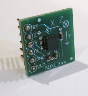
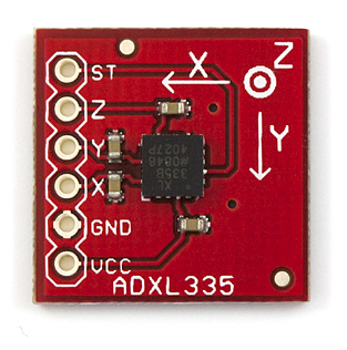
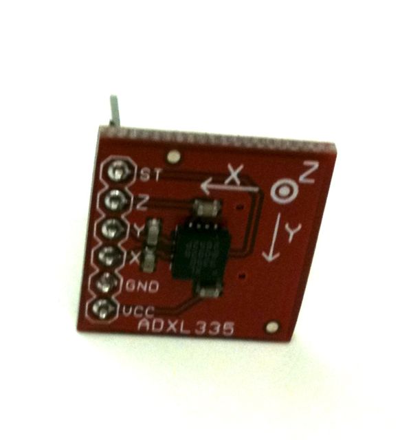
The accelerometer in your kit is a two-axis, +-2g sensor (1g is the acceleration due to gravity). It comes with 0.1" header pins that fit into the breadboard. The connections you need to make are VDD to 5V, BNG to ground, and X and Y to the first two analog input pins on the Arduino board. Pin Z is not connected to anything on the accelerometer board, and you can ignore ST (self test).
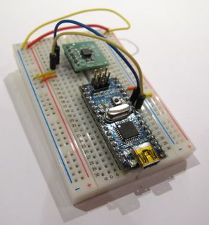
Push the accelerometer into the breadboard and make the connections as shown:
Now, get a feel for the data the accelerometer provides. Use the Light Dimmer presets, which will track analog values on A0 and A1. Then pick up the Arduino+accelerometer board and tilt it in various directions. Start by holding it so that the accelerometer board is parallel to the ground. Find in which direction the X reading increases and decreases; do the same for the Y reading.
Tilt control with an Accelerometer
The accelerometer doesn't work using a voltage divider, but it does produce an output voltage that can be connected directly to an analog input of the Arduino.
In this example, we'll simulate the motion of a ball on a tilting plane in software and control the tilt through a sensor. Think of it as a first step to build your own electronic game of Labyrinth. The right sensor to use is an accelerometer. Accelerometers can report on both static and dynamic acceleration -- think of static acceleration as the angle the accelerometer is held with respect to the ground (the acceleration measured here is due to gravity). Dynamic acceleration occurs when you shake the sensor.
The accelerometer in your kit is a 3-axis, +/- 3g accelerometer sensor. You will have to solder on a set of six 0.1" header pins to fit this into the breadboard. The connections you need to make are VCC to 3.3V power from the Arduino (this special pin is labeled 3V3 on the Arduino. Connecting to the 3.3V pin - NOT the 5V pin - is very important, otherwise you could damage your accelerometer!), GND to ground, and X, Y & Z to the first three analog input pins on the Arduino board. For more information about this accelerometer, see the links on the Sparkfun page here.
Now, get a feel for the data the accelerometer provides. Use the Light Dimmer presets, which will track analog values on A0 and A1. Then pick up the Arduino+accelerometer board and tilt it in various directions. Start by holding it so that the accelerometer board is parallel to the ground. Find in which direction the X reading increases and decreases; do the same for the Y reading.
Next, change the PD patch so that you can also read the Z axis of the accelerometer.
Tilt control with an Accelerometer
In this example, we'll simulate the motion of a ball on a tilting plane in software and control the tilt through a sensor. Think of it as a first step to build your own electronic game of Labyrinth. The right sensor to use is an accelerometer. Accelerometers can report on both static and dynamic acceleration -- think of static acceleration as the angle the accelerometer is held with respect to the ground (the acceleration measured here is due to gravity). Dynamic acceleration occurs when you shake the sensor.
The accelerometer in your kit is a 2-axis, +-2g sensor (1g is the acceleration due to gravity). It comes with 0.1" header pins that fit into the breadboard. The connections you need to make are VCC to power from the Arduino, GND to ground, and X, and Y to the first two analog input pins on the Arduino board. You can ignore the Z axis and ST (self test) pin.
Push the accelerometer into the breadboard and make the connections as shown:
Now, get a feel for the data the accelerometer provides. Use the Light Dimmer presets, which will track analog values on A0 and A1. Then pick up the Arduino+accelerometer board and tilt it in various directions. Start by holding it so that the accelerometer board is parallel to the ground. Find in which direction the X reading increases and decreases; do the same for the Y reading. Are the labels on the accelerometer board correct?


