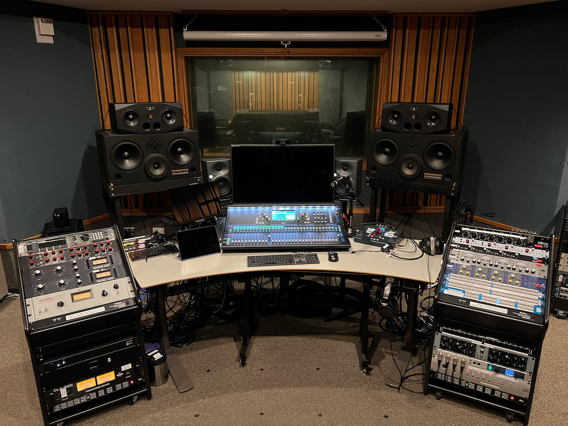
The “Recording Studio” consists of the “Control Room” (where the
recording engineers normally operate the recording technology, about
20x15 feet) and the “Live Room” (where the musicians normally perform,
about 24x17 feet), separated by a window. This section simply
inventories the two rooms; later sections explain usage, connections,
etc.
A USB-C docking station (Tobenone “Docking Station Thunderbolt 3
Dual Monitor” (manufacturer’s
page)) for the Mac Studio, providing extra USB outlets (for
removable media, dongles, etc.) and another video output (to drive the
smaller monitor).
5-octave USB MIDI keyboard (Arturia KeyLab 61 MKII Keyboard
Controller (manufacturer’s
page))((in a slide-out tray mounted underneath the table)
Three stage
boxes for connecting signals to the Control Room:
“Jupiter”, the biggest, 24 in (XLR F) for microphones, 4 out (XLR
M)
“Mars”, a smaller one (XXX)
“Pluto”, the smallest, with just 8 out (XLR M), used to feed the CAVIAR speakers.
Lots of mic stands.
Several ME-1 (manufacturer’s
page) personal monitor (headphone) mix stations (e.g., for listening
while recording) connected to an ME-U hub (manufacturer’s
page)
A window into the Control Room, acoustically and airflow shielded,
optionally able to be visually blocked.
Quick Start Guide: Control
Room
Using Your Laptop
Connect your laptop to the USB dongle marked “LAPTOP KVM-A” (on
desk, right side).
Select “LAPTOP” on KVM-A (on desk, left side).
On the USB switcher just above the KVM-A, press the “USB IN 2”
button next to “SQ-AUDIO to LAPTOP”.
In your DAW session, select “SQ Audio” as the audio interface.
On the SQ-7 (Allen & Heath mixer) recall the default scene by
pressing “Soft 16” and “This One” keys (upper right side). Also select
“Layer A” on left side, labeled as “192A Analog.”
On the RAM system (on desk, right side) select “IN 1”, turn up the
dial and unmute if needed. Select a desired “OUT”.
Using the Studio
Computer aka “Mac Blue”
Select “MAC BLUE” on KVM-A (on desk, left side).
On the USB switcher just above the KVM-A, press the “USB IN 1”
button next to “SQ-AUDIO to MACBLUE”.
Log in as “Studio User” with the password (Hint: think
backwards)
In your DAW session, select “SQ Audio” as the audio interface.
On the SQ7 (Allen & Heath mixer) recall the default scene by
pressing “Soft 16” and “This One” keys (upper right side). Also select
Layer A on left side, labeled as “192A Analog.”
On the RAM system (on desk, right side) select “IN 1”, turn up the
dial and unmute if needed. Select a desired “OUT”.
Tips & Troubleshooting
“I’m connected but not getting sound.” Check that the RAM
is unmuted and its dial is turned up. Switch to another audio device and
then reselect SQ Audio. Try recalling the default scene on the SQ-7
mixer (see quick start guide above).
“I don’t see SQ Audio as an option in my DAW’s audio device
selection on my laptop.” Try unplugging and replugging the KVM-A
USB dongle into your laptop. Also make sure that you have LAPTOP
selected on the dedicated SQ-Audio USB switcher (located just above
KVM-A on left-side of desk).
“The display monitor is not showing up.” It might just need
to be woken up; try wiggling the mouse or pressing a key on the
keyboard. Sometimes the display is turned off by accident. Its power
button is in the lower right corner and should be glowing white if
on.
How to Reset the Control
Room
Follow this checklist (also posted by the door):
Logout from the Control Room computer, “Mac
Blue” (if using).
Mute or turn down the dial of the RAM
system.
Reset SQ-7 mixer in three easy steps:
Press “soft 16” key to reset scene to “studio user” (right
side)
Press LR mix channel (right side)
Press Layer A (left side)
Unplug and put away all cables from patch
bay.
Clean up and tidy desk area.
Set the room to its DEFAULT POSITION
Put all things in their rightful places— mic stands, chairs, ME-1,
cables, etc. Use the posted signs as reference.
Turn OFF:
Phantom power (48v) to microphone preamps (if
turned on)
Both power units for mic preamps (right-side) and
outboard gear (left-side).
Talkback on SQ7 mixer (if on)
Recording in-progress light (if on).
Room lights (push in dial and twist)
Shut the outer door behind you and make sure it is
locked.
Don’t forget your things (chargers, glasses, hard drives, etc.)
!!!
Quick Start Guide: Live Room
Using Your Laptop
Connect your laptop to the USB dongle that should be hanging on the
right side of the desk.
Select “LAPTOP” on KVM-C (on desk, left side).
In your DAW session, select “Scarlett” as the audio interface.
You can either monitor from the headphone outputs of the Focusrite
Scarlett 18i20 interface which is mounted to the front of the desk or
from the Baby RAM system (on desk) which outputs to the Adam Speakers.
For the latter, be sure that “Live Room” is selected on the Baby RAM and
that the dial is raised and it’s unmuted.
Using the Live Room
Computer aka “Mac Purple”
Select “Mac Purple” on KVM-C (on desk, left side).
Log in as “Studio User” with the password (Hint: think
backwards)
In your DAW session, select “Scarlett” as the audio interface.
You can either monitor from the headphone outputs of the Focusrite
Scarlett 18i20 interface which is mounted to the front of the desk or
from the Baby RAM system (on desk) which outputs to the Adam Speakers.
For the latter, be sure that “Live Room” is selected on the Baby RAM and
that the dial is raised and it’s unmuted.
Getting
an audio signal into your DAW in the Live Room
The Live Room’s dedicated audio interface– Focusrite Scarlett 18i20,
3rd Gen– has 8 XLR inputs, two of which are on the front of the unit
(inputs 1-2) and the other 6 (inputs 3-8) are on the Switchcraft XLR
panel on the rack below the desk. Also available on this XLR panel are 8
additional inputs (9-16) that go to the outboard mic preamps that feed
through an SSL A/D converter box and are accessible in your DAW
as inputs (11-18). In order to use the outboard mic pres, turn
on the dedicated power unit on the rack and connect an XLR cable to one
of the XLR inputs on the panel. The panel is labeled but the print is
very small. Here is the order for convience…
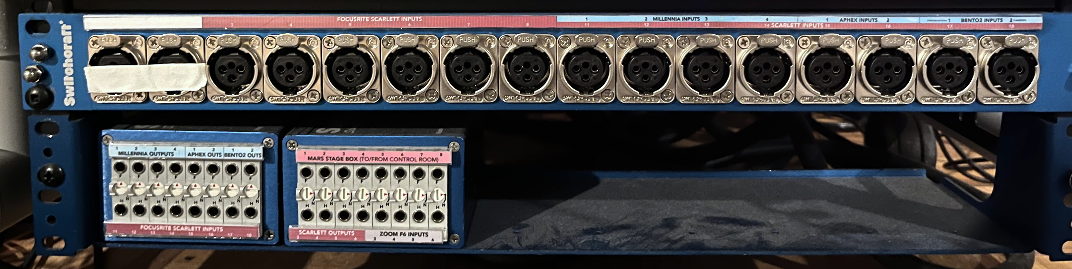
Microphone Preamps via Live Room’s XLR Panel under
desk:
Switchcraft XLR panel and patchbay in
Live Room under the desk
Inputs 1-2 = nothing; it is taped over because the first two inputs
of the Scarlett are accessible on the front of the unit itself (DAW
inputs 1-2)
Inputs 3-8 = Scarlett (DAW inputs 3-8)
Inputs 9-12 Millennia (DAW inputs 11-14)
Inputs 13-14 Aphex (DAW inputs 15-16)
Inputs 15-6 two 500-series preamps via the Bento Box (DAW inputs
17-18)
Tips & Troubleshooting
How to Reset the Live Room
Follow this checklist (also posted by the door):
Logout from the live room computer (if used).
Mute Baby RAM (rear-center of desk).
Turn off 48v for mic pres and then turn off the power for the mic
pre units.
Make sure talkback light is off (check the footswitch if it is
on).
Set the room to its DEFAULT position.
Neatly coil and tie all (purple) cables and hang them back on the
wall.
Re-open the window to the Control Room (if you closed it).
Remove personal items.
Turn off recording-in-progress light (if on).
Turn off room lights.
Shut the outside door behind you and make sure it is locked. Don’t
forget your things:)
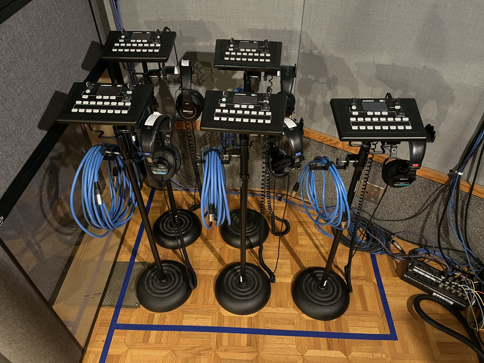
Monitoring with the ME-1
units
ME-1 units in their default position in
the Live Room
The Allen & Heath ME-1 personal monitoring units can each receive
up to 40 channels of audio from the SQ mixer via ethercon that are fed
from the ME-U Monitor Hub. The ME-1 units allow each musician to dial in
their own reference mix with the ability to balance and pan accross 12
keys. Five units live in the Live Room and one lives in the Control
Room. By default, the 12 keys correspond to the following sources:
Keys 1-8 = SQ input channels 1-8 (DAW inputs 1-8)
Keys 9-12 = Stereo DAW outputs 1-2, 3-4, 5-6, 7-8
Keys 13-15 = Aux channels 1-3 from SQ mixer
Key 16 = Talkback from Control Room
Different sources can be patched via the ME-1 units or through the
i/o routing on the SQ mixer. Note that these settings will be
overwritten when the default scene is recalled on the SQ mixer.
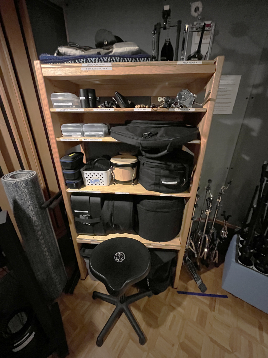
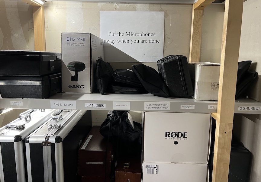
Using the Drum Kit
Drum shelving unit in Live
Room
The drum kit may be used if the instructions below are followed when
putting away the kit…
Cymbals and Stands
All cymbals go into the cymbal bag on the drum shelf.
After removing the hi-hat cymbals, keep the hi-hat clutch on
the stand. The hi-hat stand remains uncollapsed.
All other cymbal stands get half-collapsed and
remain standing in the nook. Do not lean the
stands.
Drums and other hardware
All drums go into their cases and put back to their
places on the shelving unit.
Additional hardware, such as the tom bracket mount,
goes on the shelf where labeled.
The drum throne lives in front of the shelving
unit.
Failure to follow these rules may result in losing the privilege
to use the drum kit. :(
Using CAVIAR with Mac Shrimp
Mac Shrimp is a dedicated computer for running CAVIAR (CCRMA’s virtual acoustics system) in the Live
Room. Written instructions on how to use CAVIAR in the recording studio
are currently available on the desktop of Mac Shrimp computer and Mac
Blue.
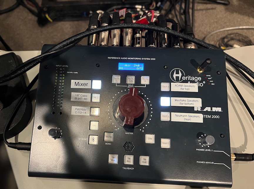
Monitor Speaker Controller
Monitor Speaker Controller in the Control
Room, with a large gain knob, labeled buttons to select input source and
output loudspeaker pair, and two pair of headphones
connected.
The Heritage Audio Reference Audio Monitoring System 2000 (aka “RAM”)
controls which stereo sound source is how loud in which of the speaker
pairs.
The huge central red dial sets the gain in clicking 1 dB increments.
The labeled buttons on the left select the input source:
Mixer (IN 1)
From the SQ7’s main left/right outputs via XLR outputs 9+10
1/8” audio (IN 2)
From a dangling 1/8” (3.5mm) TRS cable for plugging into the headphone
jack of your laptop, phone, etc.
CAVIAR stereo mix (XXX)
A stereo mixdown of the CAVIAR system’s
reverberated audio outputs; “what the people in the Live Room are
hearing.” (XXX not yet implemented)
Bluetooth (button has the bluetooth symbol)
Yes, you can choose HERITAGE RAM 2000 as a Bluetooth
“speaker” to make a convenient lossy wireless connection to control room
sound.
The labeled buttons on the right select one stereo loudspeaker pair
as the output destination:
(The vertical arrangement of the three buttons maps to the spatial
arrangement of the speakers.)
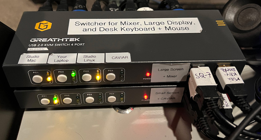
KVM Switches
KVM switches in the Control
Room
The Recording Studio contains two interconnected KVM (“Keyboard,
Video, and Mouse”) switches that control access to the mixer, three video monitors, three keyboard + mouse
sets, and a USB hub: one in the Control Room and another in the Live
Room. Each switch controls access to one video monitor plus various USB
devices, switchable among four sources (e.g., your laptop or the Mac
“Blue”).
You connect your own laptop to the studio via either of these KVM
switches.
KVM A
KVM “A” (located in the control room) controls access to these
switched devices:
Big video monitor in control room
The same HDMI signal is also split to control room send 1
primary QWERTY keyboard&mouse (the wider one with the number
pad)
Arturia MIDI keyboard
Note that the SQ7 mixer– USB audio and/or
control surface USB MIDI– no longer runs through KVM-A. Instead it has
its own dedicated 2.0 USB switcher just above it that can switch between
MAC BLUE or your LAPTOP.
KVM A connects all the above devices to any of three possible
computers in the control room:
These are wired between the live room’s “Jupiter” stage box and the
mixer’s analog inputs 1-24 (where the already-preamplified signal will
get a tiny bit more coloration from the additional gain stage of the
mixer’s preamps). By default stage box inputs 1-24 go via mic preamp
channels 1-24 (per the list above) to mixer input channels 1-24, but
everything can be rerouted through the patch
bay.
(*) Beware that the US 4-710d preamp is capable of strongly coloring
a mic signal when overdriving the tubes. For a clean sound, keep the XXX
in the XXX.
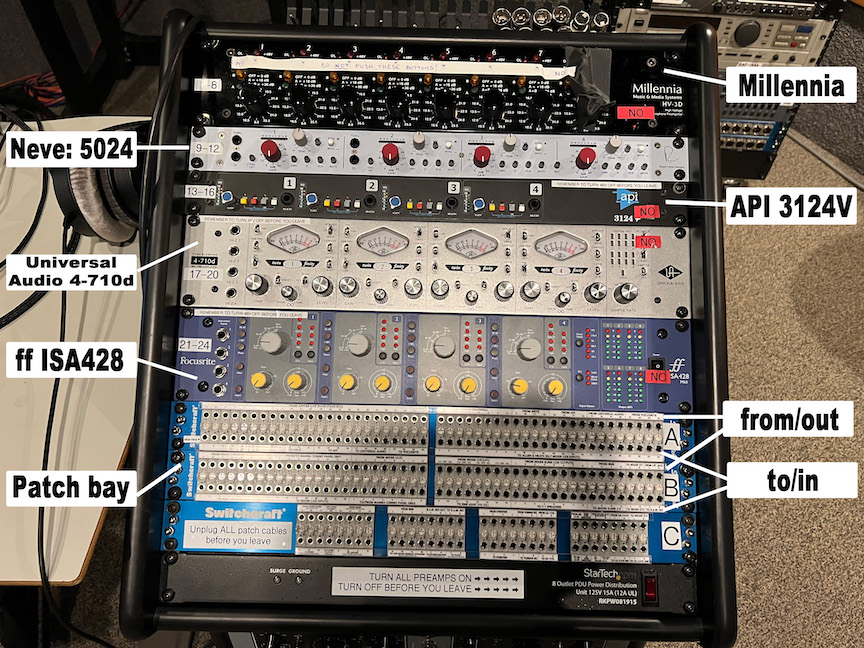
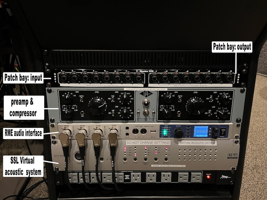
Microphone preamplifiers and patch bays
in the Control Room.
Patch Bay
The patch bay (wikipedia) provides
great flexibility in re-routing analog audio signals while also
providing a default set of “normal” connections.
To return to all default signal connections, simply remove
all cables from the front of the patch bay.
In general, a patch bay has connections on the front (the “points”
where users can patch and repatch) and on the back (permanent
connections with specific inputs and outputs of specific audio
equipment). These come in top/bottom pairs, i.e., the front of each
patch bay has two horizontal rows of points.
By convention, signals coming from equipment’s outputs connect to the
top of patch bay pairs, while signals going to equipment’s
inputs connect to the bottom, as if gravity were helping
signals tend to flow down from the top row to the bottom row.
(Actually the notion of “to” and “from” is more of a metaphor about your
patching intentions: the patch bay really just creates direct
electrical connections among whatever is plugged into it, with no
inherent direction; it would not be wrong (though confusing) to say that
the patch bay connects “to” all the various equipment. Also
terminology can be confusing when mixing up the equipment’s
point of view versus the patch bay’s point of view, e.g., an
“output” “from” the patch bay going “to” a preamp “input”. We recommend
thinking in terms such as “using the patch bay to connect this
microphone’s output to that preamp input.”)
The main thing to avoid is patching an output to another
output. An “output” on a piece of gear means that it is
“trying” to put a certain time-varying voltage (between the “signal” and
“ground” connections) by pumping out as much current as necessary to
drive whatever impedence it’s plugged into. Bad things happen when two
or more different pieces of equipment try to do that at the same time to
the same point in the circuit.
Three possible normalization
modes determine how plugging into the front affects a possible default
connection between the two signals plugged into the back:
“Full normal”: The back signals are connected to each other unless
either front point is plugged in.
“Half normal”: The back signals are connected to each other if
neither front point is plugged in. If the upper front point is
plugged in then the signal is split (passively, in analog, with signal
loss) so that one (diminished) “copy” from the upper rear goes to the
lower rear, and another (diminished) “copy” goes along the patch cable
connected to the upper front point. If the lower front point is
plugged in, then only that goes to the lower rear and no splitting
occurs.
“Non normal”: There is never any connection between the back
signals, no matter how the front is connected.
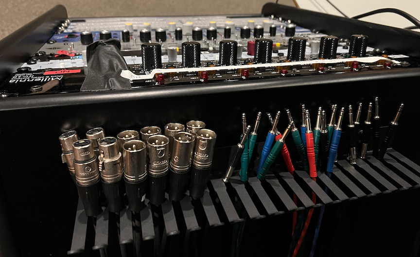
All patch bays in the CCRMA recording studio use “TT”
(aka “Bantam”) connectors for the front points. These appear quite
similar to 1/4” (7mm) TRS audio, but are slightly smaller and with a
different shape that tends to avoid clicks when making and breaking
connections. (On the rear are DB25 aka
D-sub connectors each plugged into an 8-channel snake.) A small
assortment of adapter cables between TT and either XLR or 1/4” TRS allow
you to plug equipment directly into the front of the patch bays:
Top-view of preamp/patchbay rack showing
the default/reset condition with all the patch cables put away in the
holders and nothing plugged into the front of any patch
bay.
Naming convention: The three patch bays are simply
A, B, and C. Each
consists of a good number of “slots” numbered left-to-right from
1 to 48. Each slot consists of two points:
Upper and Lower. So the name of a
particular front-facing patch bay point will be of the form
B23U, in this case meaning “Patchbay B, slot 23, upper
point.”
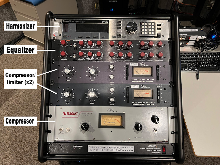
Upper portion of rack containing effects
accessible via the patch bayLower portion of the same rack, showing
some XLR/7mm jacks and a UA 2-610 tube preamp (accessible via the patch
bay) as well as the CAVIAR audio interfaces and some user-accessible AC
power outlets.
Studio Computer
CCRMA maintains a desktop Macintosh computer in the Control Room,
primarily for recording and mixing.
You can log in with your CCRMA user account, which
will load your home directory (including Desktop, Documents, etc.)
remotely over the network. Don’t try to record or play back audio to
this networked disk; instead use a “local” drive physically plugged into
the machine.
The best practice is to bring your own and plug it into the machine
via USB.
Otherwise you can use our local disks. Someday they will be backed
up. Someday we will delete your files.
Each room has two crazy button-dials, one for “on” and one for “off”,
independently controlling 12 “channels” of lights. When you press the
“on” button-dial, the currently-dialed channel turns on, and likewise
for the “off” button-dial.
Maximum light
Press in “on” button-dial and keep it pressed in while spinning through
all 12 numbers
Minimum light
Press in “off” button-dial and keep it pressed in while spinning through
all 12 numbers
Select light
Turn each of the 12 channels on or off as desired
RECORDING lights
Simple on/off horizontal toggle switch for the “Recording” lights that (by
social convention) prevent other people from entering each room.
CAVIAR
“CAVIAR” is Eoin Callery’s cute acronym “Center for
Augmented/Virtual/Interactive Audio Realities” to describe CCRMA’s
in-house system for adding reverb to the live sound in a room via
microphones and loudspeakers that magically don’t howl with horrible
feedback sounds.
Front-facing XLR female recording inputs (to the above devices)
Front-facing XLR male playback outputs (from the above devices)
Note that nothing is wired permanently to the main audio system; we
imagine you will connect from these front-facing XLR connectors to the
patch bay if you’re crazy enough to want to use
any of this.
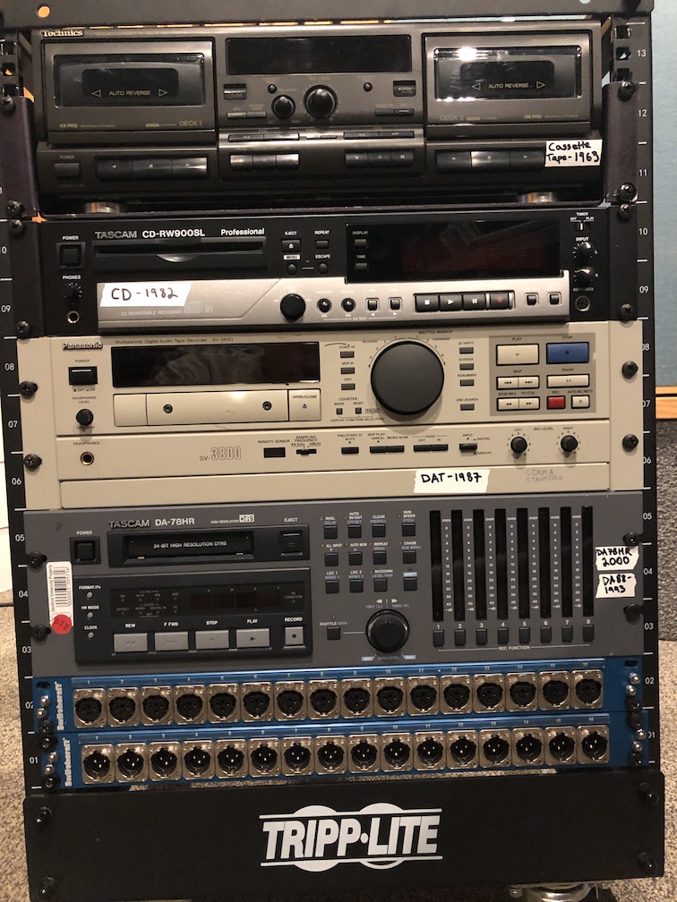
Historical
There was lots of good documentation for the old Recording Studio
(which instead centered a Yamaha DM2000 mixer and a Mac Pro (cmn44,
“Late 2013” “trashcan” style, 3.7 GHz Quad-Core Xeon E5, MacOS “Sierra”
10.12.6)); this now all needs to be carefully combed through to preserve
the still-true bits in new documentation:
The old
Recording Studio Room Guide was current as of Sept 2019, including
equipment list, typical routing, etiquette, lighting, and links to the
next two guides:
Eoin Callery’s Recording
Studio Quick Guide has lots of step-by-step instructions with
pictures for accomplishing common tasks in the Recording Studio, and was
current until August 2021.
.JPG)